by John S. Belrose
The Radioscientist -- volume 5 number 3 September 1994
|
. |
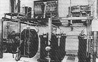
| A laboratory version of a Braun-type spark transmitter. (Janice Lang, Communications Research Centre) |
Many scientists and engineers have contributed to the development of electromagnetic theory, the invention of wireless signalling by radio and the development of electromagnetic antennas needed to transmit and receive the signals.
Concerning the history of wireless communications, several names stand out above the others. The very possibility of wireless communications is founded on the researches of Clerk-Maxwell into the mathematics of electro-magnetism, researches so "pure" and abstruse that it took mathematicians several years to appreciate their significance.
Today Maxwell's equations form the basis of computational electromagnetics. In the experimental verification of the results foretold by Maxwell's theory, use was made of the results of experiments in pure physics which Lord Kelvin had made forty years previously. Kelvin had set himself the task of investigating the way in which a Leyden Jar discharged and found that, under certain conditions, the discharge gave rise to alternating currents of very high frequency.
Forty years later, Hertz was able to utilise these high frequency currents to produce the first wireless waves, thus validating the theory of Maxwell.
Marconi was the first to describe and the first to achieve the transmission of definite intelligible signals by means of Hertzian waves. History has accredited him with the invention of an early form of radio telegraphy. His contributions to the history of radio communications are well known and celebrated but other experimenters took a hand, very early.
Do you know:
The answer to all seven questions is Reginald Aubrey Fessenden, a Canadian-born radio pioneer, working in the United States. Fessenden must clearly be the pioneer of radio communications as we know it today. I wonder how many of you have heard of him?
It is perhaps appropriate that an Alexander Graham Bell Lecture should remember the contributions of Prof. Fessenden to the early history of radio science, since the work of Bell had a profound influence on his life. Bell developed a method of sending words over wires (the telephone). The idea of transmitting the human voice by wireless dominated the early radio experiments of Fessenden.
Reggie, during his boyhood in Fergus, Ontario, followed the work of Alex Bell in nearby Brantford with great fascination. But his inquisitive mind was well ahead of Bell's experiments.
The year was 1876, Reggie was 10 years old. His Uncle Cortez Fessenden, who played an important role in the development of Reggie's inquiring mind, had been invited to see a demonstration of the telephone at the Bell homestead on 4th August. Bell's first long distance call, between Brantford and Paris, via Toronto, a distance of 113 kilometres, was made a few days later on the 10 August 1876.1
Reggie could hardly wait to meet his uncle after the demonstration to find out how it worked. In a conversation with his Uncle Cortez on the following day, which took place during a thunderstorm, Reggie was seeking an understanding about the transmission of sound over wires (the telephone).
"Uncle, how far do you think the roar of thunder call be heard? And have you noticed it comes booming down without a single wire to help it?"
"The thunder doesn't need a wire because it travels to us on a sound wave; with lightning it is an electric wave."
"Then why doesn't Bell shout on a wave?"
"He does. Bell gets his electric waves from a storage battery and those waves shuttle back and forth on the wire thus carrying his voice."
"But why is the wave on the wire. It strikes me that those wires are a crazy nuisance, the thunder doesn't need a wire, so why does Bell need one?"
"Heaven knows what direction his words would take without something to guide them," his uncle replied. "Is it not plain to you, lad, that the thunder is only a sound wave? Why, it wouldn't travel any distance at all unless you loaded the whack on a wave of electricity."
Cortez was not entirely satisfied with his answers to "Why a wire?" Being a good physics teacher, he was up on mathematics, and it appeared to him that there should be some way of using mathematics to explain the working of electricity and words and wires, but he had to admit to himself that it was simply beyond his ken.
"Words without wires," Uncle Cortez mused to himself. "I have never heard of such a nonsensical thing." But his Uncle Cortez and the world would, when Reggie grew up.
Years later, in 1897, Reginald, now 31 years old, was again having a discussion with his uncle. "Look," he said. He threw a rock into Chemung Lake, near Peterborough, Ontario.
"See how the waves circle out where the rock hit? If they are going to carry the whole range of voice sounds, the Hertzian waves must radiate like that from the antenna at the transmitting end, and they must keep going in a steady stream until they encircle the antenna at the receiving station. They must never let up even for a split second."
"I see," said his uncle. "In Marconi's scheme, they stop and go, stop and go."
Suddenly, after minutes of silence, Reg said, "Continuous. That's the word that describes them, 'Continuous Waves'."4
And so our present continuous wave approach to radio communications was born. But generating CW, modulating the waves, and receiving them was yet to be accomplished.
Pre-radio science career
Reginald Fessenden may well be the greatest Canadian-born scientist, inventor and engineer. As a scientist he should be considered the intellect, peer of Lord Rutherford, Sir J.J. Thompson and Lord Kelvin. Oliver Heaviside and, particularly, A. E. Kennelly (co-discoverers of the Kennelly-Heaviside ionospheric layer) were his contemporary colleagues.
As an inventor, he held some 230 patents. As an engineer, he did not confine his expertise to one discipline but worked with equal facility in the chemical, electrical, radio, metallurgical and mechanical fields. Yet in spite of his brilliance, the number, and the continuing usefulness of his contributions, he is now virtually forgotten, except by a few.2, 3, 4, 5, 6, 7, 8 In Susskind's9 comprehensive review of the early history of electronics and wireless, no mention was made of him.
| . | 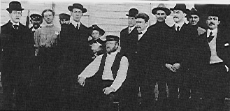 |
| The Brant Rock staff and operators. Fesssenden is seated in the middle and to his right is his son (Reginald Kennelly), holding Mikums, his cat. Mr. Pannill is on the far left. Standing next to him is Jessie Bent, the secretary. Mr. Stein is on the far right. (Radioscientist) |
Reginald Aubrey Fessenden was born in Knowlton, Brome County, Canada East (now Quebec) on 6 October, 1866. The family resided at East Bolton (now Austin) at that time. In 1871 the family moved to Fergus, Ontario, and in 1875 to Niagara Falls, Ontario.
Educationally, the young Fessenden was a prodigy. He attended De Veaux Military Academy, Niagara Falls, New York, for one year at the age of nine. He went to Trinity College School, Port Hope, Ontario, where he won prizes and the praise of the headmaster as one of the best students that he had ever had. At the age of 16, he accepted a mathematics mastership at Bishop's College, Lennoxville, Quebec, where he became interested in science through private reading of the periodicals Nature and Scientific American.
In 1886, he accepted the principalship of Whitney Institute, Bermuda. Although he never lived in Canada again, he considered himself a Canadian, and he spent vacations at his uncle's cottage near Peterborough, Ontario.
Fessenden worked at Thomas Edison's laboratory, East Orange, New Jersey, from 1887-1890. When Edison gave him the task of producing a nonflammable insulation for electrical wires, Fessenden set out to learn all he could about elasticity. The recognized authorities on the subject were Sutherland and Lord Kelvin, who held the view that both elasticity and cohesion were due to a gravitational attraction between the atoms. Fessenden was skeptical, and began a research study for a better explanation. Using mathematics as a basis for his study, Fessenden concluded that atoms had to be spherical in shape, with a positive charge at their centres and a negative charge on their surfaces. He considered atoms as electrostatic doublets.
In a series of technical notes Fessenden proposed his electrostatic doublet theory of cohesion, and used it to calculate the physical and electrical properties of metals, reportedly showing that the cohenion, rigidity and Young’s modulus came out right.10,11 His paper entitled "The Law and Nature of Cohesion," published in 1892, was deemed preposterous by contemporary scientists, including Sir J.J. Thompson, Cavendish Laboratory, Cambridge, on the grounds that since metals were conductors, the individual atoms must also be conductors and could not contain internal charges! Ironically it was Sir J.J. Thompson who, five years later, demonstrated that atoms were electromagnetically constituted.
In 1890, Edison encountered financial difficulties, and Fessenden was laid off. He went to work for Westinghouse. Here he tackled different problems. The method of using platinum connecting wires for an electric lamp made light bulbs expensive, and was covered by a patent. Fessenden found ways of fusing wires of iron or nickel alloys to the glass, greatly reducing the price. This breakthrough was a significant early step in the transition of electric light from a novelty to an everyday necessity.
He later developed silicon steel. Early transformers and electric motors were lossy due to hysteresis loss in the iron cores of the transformer and iron pole pieces in motors.
| . | 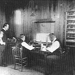 |
| Inside Brant Rock: Fessenden is seated at right. (Radioscientist) |
Fessenden reasoned that replacement of the large carbon atoms in the steel by smaller silicon atoms would reduce the hysteresis loss, and in almost a century, no better method has been found than his silicon steel.
In 1892, he accepted the chair of electrical engineering at Purdue University, and although he stayed there for only one year, he was responsible for establishing the Electrical Engineering Department at the university, and his influence is perhaps still felt today.12
In 1893, the University of Pittsburgh persuaded him to accept the same chair in that city, largely because George Westinghouse was anxious to have Fessenden nearby and helped with a substantial honorarium.
In 1899, Fessenden attempted to return to Canada, but McGill returned his application for the chair of electrical engineering. The position was filled by a "professor" from Nebraska.
Fessenden never did graduate formally from a university, but because of the positions he held with Purdue University and the University of Pittsburgh he was hereafter referred to as Professor Fessenden. One can only speculate what might have happened if he had worked at McGill with Rutherford and Soddy.
Fessenden's inventive mind was already in evidence. By 1901, he already held nine patents with respect to incandescent lamps. His hobby of photography led him to the invention of what he called microphotography, an early form of microfilm. He also began experimenting with radio waves, and it is in the field of radio science that Fessenden made his greatest contributions.
Wireless telegraphy
Fessenden closely followed the work and research methodology of Heinrich Hertz, Thomas Edison and Alexander Graham Bell.
In 1900, he joined the US Weather Bureau, which sought a system for transmitting weather forecasts. Unfortunately, he soon fell out with his superior at the bureau and resigned in August 1902.
In September, he secured the financial support of two Pittsburgh millionaires, T.H. Given and Hay Walker; and together they formed the National Electric Signalling Company (NESCO). While the partnership eventually collapsed (in 1912), Fessenden's greatest achievements occurred under its aegis.
It is interesting to note that Fessenden, in 1905, established the Fessenden Wireless Telegraph Company of Canada. Unfortunately, this venture never went anywhere. The Canadian Company never received support from his American partners. It acquired a transatlantic license from the British government, but not from Canada. Only Marconi was licensed to erect towers in Canada and install radio equipment in Canada - a senseless Government regularity ruling that held back the competitive development of radio in Canada for more than two decades.
Marconi, for his transatlantic experiment in December 1901, employed a Braun type of antenna system, see below, and a spark transmitter designed and constructed by Fleming.
Marconi knew very little about his transmitter. It is interesting to speculate on whether Marconi drew the hand-drawn sketch of "his" transmitter, labelled Marconi's transmitter, published in a 50th anniversary publication of the IEEE on the early history of wireless. This "transmitter" simply would not work.
Ratcliffe13 has discussed scientists' reaction to Marconi's transatlantic experiment. The author has also pursued this subject. He modelled Marconi's Poldhu antenna system to determine its frequency of oscillations. But that is another story.
The technology of the era as exemplified by Marconi systems was based on the generation of radio waves by creating a spark, which can be likened to a whiplash effect. Let us digress for the moment and speak about spark-transmitters.
Spark transmitters
The simplest method of producing high-frequency oscillations is to give an electrical shock to an oscillatory circuit consisting of an inductance and a capacitance in series. This principle is used in the so-called spark transmitter.
 |
. |
| Sketches illustrating actual and equivalent circuits for spark transmitters. (Radioscientist) |
Hertz’s transmitter, in 1888, placed the spark gap across the terminals of the antenna, which was an endloaded dipole. The equivalent circuit of an antenna at frequencies near its self-resonant frequency is a series-resonant circuit (La - Ca -Ra)
Marconi, following the lead of Hertz, employed such a spark transmitter, but his antenna was a monopole type, a wire fed against ground. Since the only conducting path for the transmitting antenna to ground was by way of a spark across the gap, the oscillations on the antenna were in very short bursts.
The natural L-C-R response of the antenna system was interrupted when the spark discharge ceased. The only connection to ground was through the low impedance of the spark discharge. But this cap was considered to be an essential element of the radiating system. Indeed, some contemporary mathematicians concluded on the basis of their "theoretical" studies that no antenna could radiate without a gap!
This not-wanted gap was eliminated by Braun, a German physicist, who in 1898 patented a circuit in which the spark gap was in a separate primary circuit in series with an appropriate coil and condenser.
But the contribution of the Braun patent is perhaps as controversial as is the subject of who was the first to devise electromagnetic antennas. The German patent has been questioned. Nothing original was said about tuning, and the oscillating circuit was said to be much "slower," tuned to a lower frequency, than the antenna circuit.
If the coupling between the oscillating and antenna circuits is high, a double peaked amplitude frequency response will result, and while such a response is not wanted, both circuits should certainly be tuned to the same frequency. I say "not wanted," because this double-hump response in effect made the transmitter transmit a "double wave."
In fact, early radio regulations were introduced encouraging "single-wave" or "sharp" emissions, by limiting the amplitude of the second wave to say one-tenth the amplitude of the stronger, desired wave. Notwithstanding, Braun's "tank circuit" was coupled inductively to a secondary consisting of the antenna in series with a coupling coil in which the driving electromotive force was induced and which provided a continuous conducting path from the antenna to ground. Except for the later insertion of a transmission line between the antenna and the coupling coil, the Braun antenna arrangement provided the complete electrical equivalent of the present-day base-driven monopole antenna.
A Braun-type spark transmitter was a considerable improvement over the "simple" or "Marconi type transmitter." It consisted of a condenser and an inductor in series with a spark gap, across which is connected an induction coil.
The induction coil had a low-voltage primary winding and a high-voltage secondary winding.
| . |  |
| An early version of Fessenden's synchronous rotary spark gap transmitter. (Radioscientist) |
The low-voltage primary winding was driven by a battery and an interrupter, which made and broke the connection of the primary winding to the at some low audio frequency rate.
When the induction coil was working properly the condenser was charged up, and when the potential across it was sufficiently high to break down the insulation of air in the gap, a spark then passed. Since this spark has a comparatively low resistance, the spark discharge was equivalent to closing of the oscillatory L-C-R circuit.
The condenser now discharged through the conducting spark, and the discharge current took the form of a damped oscillation, at a frequency determined by the resonant frequency of the spark transmitter. The RF energy flowing in the inductor was inductively coupled to an antenna, which was tuned to the same frequency as that of the spark transmitter.
The induced oscillation in the antenna circuit was also a damped wave, but the period of oscillation was significantly longer than the oscillation in the primary. In effect, the primary is the "tank circuit" and the secondary the "antenna circuit."
Marconi's early telegraphy experiments were made using such a spark transmitter. However, it was with the simple form of transmitter, spark gap across the antenna terminals, that he obtained his first successful results and demonstrated the possibility of wireless telegraphy by means of electromagnetic waves propagated over great distances.
The interrupter was a mechanical device, operating at a rate corresponding to a low audio frequency. Thus, each time the key was pressed the receiver would "hear" a buzz (ignoring for the present that a suitable detector so that the operator could actually "hear" the sound of the transmitted signal had not been devised). The audio sound to be "heard" was the interrupter frequency accompanied by the ragged and irregular noise of the spark-generated signal.
Most early radio experimenters followed or improved upon the Marconi method of signalling because in their view a spark was essential to wireless. But later experimenters employed an AC generator and a high-voltage step-up transformer, rather than an induction coil and battery, for the power source.
Fessenden’s work in radio was important, not only for the results he secured, but because of its originality. From the outset he sought methods to generate and receive continuous waves, not damped waves which started with a bang and then died away quickly. However, his early experiments had to make do with spark transmitters, the only means known at that time for generating appreciable power.
So he set his mind to make this type of transmitter more CW-like. This led to his development of the synchronous rotary spark-gap transmitter. An AC generator was used, which as well as providing the energy for the spark transmitter, was directly coupled to a rotary spark-gap so that sparks occurred at precise points on the input wave. The spark was between a fixed terminal on the stator and a terminal on the rotor, in effect the rotor was a spoked wheel, rotating in synchronism with the AC generator.
Thus, a higher spark rate was achieved, high compared with the frequency of the AC generator. But another advantage was realized, since in effect a rotary spark cap was a kind of mechanically quenched spark cap transmitter.
The oscillations of the primary circuit ceased after a few cycles, since when the rotating gap opened the spark ceased, and the antenna circuit continued to oscillate with its own damping. The quenched spark gap was more efficient, probably a less noisy, narrower-band signal compared with the unquenched gap, since any of the spark methods of excitation inherently involve consumption of energy in the spark, in addition to the energy losses occurring in the antenna circuit.
 |
. |
| The Brant Rock synchronous rotary spark gap transmitter. (Radioscientist) |
Many forms of quenched spark gap transmitters were devised, described as Wein transmitters, but the Fessenden synchronous rotary spark-gap transmitter was perhaps the best. With a synchronous spark-gap phased to fire on both positive and negative peaks of a 3-phase waveform, precisely on the peak for maximum efficiency, a 125 Hz AC generator would produce a spark rate of 750 times a second. These rotating gaps produced clear almost musical signals, very distinctive and easily distinguished from any signal at the time. It was not true CW, but it came as close as possible to that, and the musical tone was easily read through atmospheric noise and interference from other transmitters.
His Brant Rock station employed a synchronous rotary spark gap transmitter, the latest one built to date. It was completed on 28th December 1905. The rotary gap measured 6 feet in diameter at the stator and 5 feet in diameter at the rotor. Its rotor had 50 electrodes (poles), and its stator had four. Coupled to this rotary gap was a 125 Hz, 3-phase, 35 kVA alternator.
HF alternator for CW
Spectacular as was the Brant Rock transmitter, Fessenden, after achieving initial success (to be described) soon turned his attention to other directions, devoting his efforts to newer and better developments: the HF alternator.
Fessenden realized, as we have already noted above, that this stop-and-go system, the spark transmitter, was incapable of transmitting satisfactorily voice and music. A means of sending and receiving continuous waves was required.
The idea came to him during discussions with his uncle Cortez Fessenden, as I have already told you, while visiting with him at his cottage on Chemong Lake near Peterborough in 1897, and is described in his US Patent No 706737, dated August 12, 1902.
But it was not before the fall of 1906, when Fessenden's HF alternator was developed to a point where it could be used practically (frequencies up to 100 kHz were possible), that continuous-wave transmission became feasible.
Marconi and others working this new field of wireless ridiculed Fessenden's suggestion that a wireless signal could be produced by applying an HF alternating current to an antenna. All were unanimous in their view that a spark was essential to wireless, an error in reasoning that delayed the development of radio by a decade. Fessenden was right, but alone in his belief. "The whip-lash theory however passed gradually from the minds of men and was replaced by the continuous wave one with all too little credit to the man who had been right."14
To document the reaction of his colleagues to this departure from conventional transmission methods, spark or damped wave transmissions, we can note that J.A. Fleming, in his book Electromagnetic Waves, published in 1906, said, in reference to Patent No 706737, that "there was no HF alternator of the kind described by Fessenden, and it is doubtful if any appreciable radiation would result if such a machine were available and were used as Fessenden proposes."
Fleming was totally wrong, since 1906, the year in which his book was published, was the year of Fessenden's greatest achievements using continuous waves generated by an HF alternator, with one terminal of the alternator connected to ground and the other terminal to the tuned antenna. Certainly, the referenced statement did not appear in subsequent editions of Fleming's book.
Judge Mayer, in his opinion upholding Fessenden’s patent on this invention, said, "in effect it has been established that the prior art practiced, spark, or damped wave transmission, from which Fessenden departed and introduced a new or continuous-wave transmission, for the practice of which he provided a suitable mechanism which has since come into extensive use."15
Initially, Fessenden employed various forms of arc transmitters and rotating spark cap transmitters with varying degrees of success. When he had perfected his HF alternator in Fessenden had achieved his goal, viz a continuous wave transmitter, the frequency of which was not determined by aerial tuning but by the speed of the HF alternator. The aerial tuning only determined the power transfer from his transmitter to the aerial. Subsequently, the HF alternator was replaced by vacuum-tube transmitters, and nowadays by solid-state transmitters, but the basic principle of operation of the Fessenden transmitter is the same as that today.
As early as 1890, Tesla built high-frequency alternating current (AC) generators. One, which had 384 poles, produced a 10 kHz output. He later produced frequencies as high as 20 kHz.16 There is no fundamental reason that such frequencies could not have been used for worldwide wireless communications; in fact, in 1919, the first continuously reliable transatlantic radio service, with a transmitter installed in Brunswick, New Jersey, used a 200 kW HF alternator operating at a frequency of 21.8 kHz. However, practical antennas used in the early days of radio were not large enough to radiate efficiently at such a low frequency, so LF rather than VLF had to used.17
Fessenden contracted the GE Company to build an HF alternator operating at speeds of 50-100 kHz. Alexanderson struggled for two years to develop such a machine, and in September 1906, GE delivered his best effort - which in Fessenden's view was a "useless machine."
The Alexanderson alternator did not meet Fessenden's specifications. The GE alternator was returned with a letter stating that in the opinion of its engineers it "could never be made to operate above 10,000 cycles"21. It is not clear what had been improved over the Tesla alternator.
So Fessenden took upon himself to rebuild the machine. He must have persevered, day and night, in the usual way he attacked a problem, since by November 1906, he had a machine that would operate at frequencies in the 50-90 kHz band.
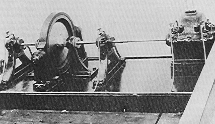
The Fessenden high frequency alternator was a small machine of the Mordey type, having a fixed armature in the form of a thin disc, or ring, and a revolving field magnet with 360 teeth, or projections (see below). At a speed of 139 revolutions per second, an alternating current of 50,000 Hz and a terminal EMF of 65 volts was generated. The maximum output of the alternator at the above speed was about 300 watts20.
Very little difficulty seems to have been obtained in running the machine at so high a speed. A simple flat belt drive was used, powered by the steam engine at Brant Rock, and a thin self-centring shaft which entirely eliminated excessive vibration and pressure on the bearing. The belt and the step-up gear box can be seen on the far right of the photograph, the alternator is on the left. The frequency of the alternator was determined by the speed of the steam engine, which had to be well regulated.
Fessenden later developed a high frequency alternator that had an output of 50 kW. This machine was scaled up to 200 kW by the GE company, and put on the market as the Alexanderson alternator, named after the man who supervised the job. History forgot that Fessenden developed the prototype.
| . | 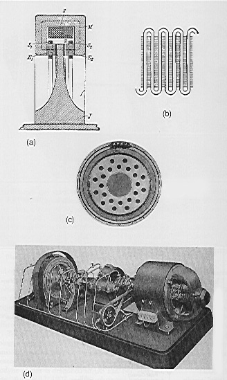 |
| Figure 1: The Fessenden-Alexanderson HF alternator: (a) diagrammatic cross-section of one of these alternators; (b) the armature winding in which the EMF was induced; and (c) one half of the completed armature. (Radioscientist) |
Zennick22 has detailed the early efforts to develop this high frequency alternator, and described the principle of its operation. Figure 1a is a diagrammatic cross-section of one of these alternators. The excitation is obtained by means of a single large field coil, S, which is wound around the entire machine and supplied with direct current. The magnetic flux lines, M, of this coil pass through the iron cores, E1 and E2, of the armature coils, S1 and S2. The only moveable part, J, has teeth or projections, Z, of iron, at its periphery. When one of these teeth is just between the armature coils, S1 and S2, the magnetic flux, M, has a path almost entirely through iron, excepting for the very small air gaps between the teeth, Z, and the cores, E1 and E2. In this position then, the magnetic reluctance is a minimum, and the magnetic flux passing through cores E1 and E2 a maximum.
When now a space instead of a tooth lies between the armature coils, the air gap, and hence the reluctance are much larger, so the amount of flux through the armature windings is very small. Hence as the moveable part J rotates, the magnetic flux varies periodically between a maximum and a minimum value, so an oscillatory EMF is generated, whose frequency = the product of speed in revolution/second x number of teeth, is induced in the armature windings. The rotor of the Fessenden-Alexanderson machine is shaped like the cross-section J, in Figure 1a. The rotor of the machine shown in Figure 1d with its DC motor had 300 teeth. The space between the teeth was filled with non-magnetic material (phosphor-bronze) so the surface of the rotor, J, was quite smooth, thereby preventing any loss due to air friction (windage). The armature windings S1 and S2, in which the oscillatory EMF was induced did not properly consist of coils, but a single wire wound in a wave shape form.
 |
. |
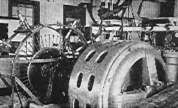
| Fessenden's HF alternator. (Radioscientist) |
Any two consecutive U-formed wires could be considered as a pair of coils of one turn each, joined in series but so as to oppose each other. Figure 1c shows one half of the completed armature.
One of these early machines is shown in Figure 1d. Here the drive is an electric motor. The photograph shows three main parts to the whole set up, from right to left, the electric motor, a step up gear box (which Fessenden refers to as a de Laval gear in connection with his alternators) and the alternator on the far left. Clearly the alternator shaft and the motor shaft are not in the same line, the difference being taken up by the gear box. The small object in front (and driven by a flat belt) is an oil pump to ensure lubrication of all high speed bearings. The capacity of the alternator increases as the air gap between armature and rotor is decreased. It was 2.1 kW in one machine having an air gap of 0.37 mm.
Receiving continuous waves
The use of CW created problems for Fessenden, not only in regard to the generation of continuous waves but for reception. First, at a distant station where the received signal was weak, and if it were receivable at all, one had to find and tune the receiver to this narrowband signal in the expanse of unused radio spectrum. The broadband spark signal was more easily found. Second, the coherer-type detector used for reception of spark transmission was useless for detecting CW. Fessenden was convinced that the successful detector for wireless signals must be constantly receptive, instead of requiring resetting as was characteristic of the coherer. But this was more easily said than done. He first devised a hotwire barretter, similar in nature to a miniature lamp of which the filament was made of Wollaston wire. From it he produced, as a result of an accident during the process of making his hotwire barretter, a liquid barretter.
The hotwire barretter needed to have the silver coating removed from a very short length of the wire by a nitric-acid treatment. It was during such treatment that Fessenden observed that one of several such barretters, in this silver-dissolving part of the process, was giving indications on a meter attached to the circuit of signals received from an automatic test sender sending "D"s.
An examination revealed that this one had a broken filament, while the others were complete. A brief investigation disclosed the fact that this Wollaston wire dipping into the 20% nitric-acid solution was far more sensitive and reliable than any other known type.
The word barretter was coined by Fessenden from his classical language background. The term is a derivation from the French word exchanger, implying the change from AC to DC. For proper operation, the platinum-coated Wollaston wire needed to make point contact, lightly touching the acid solution (refer US Patent No 727331, 5 May 1903 for the basic detector; and No 793684, December 1904 for a sealed detector for shipboard use).
This detector was the standard of sensitivity for many years, until it was replaced by the galena crystal detector, and by the vacuum tube in about 1913. This detector, when used with a telephone receiver in a local shunt circuit, gave such accurate reproductions that radio operators could identify several wireless telegraphy stations in the passband of the receiver by the different characteristics of the spark transmissions, just as a friend's voice is recognized by its peculiarities of tonal quality. And it made possible subsequently the reception of radio telephony (voice).
It is interesting to read a paper by Leslie A. Geddes, Purdue University, entitled "The Rectification Properties of an Electrode-Electrolyte Interface Operated at High Sinusoidal Current Density"18 for a modern analysis of the Fessenden barretter type of detector. The authors became aware of Fessenden's pioneering work only after acceptance of their paper by the Journal.
Fessenden's telegraphy transmissions employed a synchronous rotary spark-gap transmitter, which was in effect a modulated quasi-CW method of signalling, well suited to detection by rectification. But this rectifier-detector was useless for the reception of unmodulated continuous waves. All that would be heard would be clicks, as the Morse key was closed and opened.
Again Fessenden's fertile mind worked around this problem. He devised the methodology of combining two frequencies to derive their sum and difference frequencies, and coined the word heterodyne, derived from the joining of two Greek words hetero, meaning difference, with dyne, meaning force. Today, heterodyning is fundamental to the technology of radio communications. Some radio historians consider that his heterodyne principle is Fessenden's greatest contribution to radio science. His initial heterodyne circuit is described in US Pat No 706740, dated 12 August 1902 and his advanced heterodyne circuit, Pat No 1 050 441 and 1 050 728, is dated 14 January 1913.
Armstrong's superheterodyne receiver is based on the heterodyne principle. Except for method improvement, Armstrong's superheterodyne receiver remains the standard radio receiving method today.
Spark telephony
Fessenden's one desire was to transmit voice without wires. In 1899, while experimenting with spark transmission employing a Wehnelt interrupter operating the Ruhmkorff induction coils, Fessenden noted that, when the telegraphy key was held down for a long dash, the peculiar wailing sound of the Wehnelt interrupter was reproduced with good clarity in the receiving telephone. This at once suggested that by using a spark rate above the voice band, wireless telephony could be achieved.
 |
. |
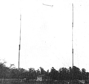
| Twin radio towers at Cobb Island. (Communications Canada) |
Professor Kintner, who was working for Fessenden at that time, designed an interrupter to give 10,000 breaks a second, and this interrupter was built by Brashear, an optician. The interrupter was delivered in January or February 1900, but experiments were not conducted until the fall of that year. To modulate his transmitter, he inserted a carbon microphone directly in series with the antenna lead. After many unsuccessful tries, transmission of speech over a distance of 1.5 km was finally achieved on 23 December 1900, between 15-metre masts located at Cobb Island, Maryland.
The received telephony transmission was reported to be perfectly intelligible, but the speech was accompanied by an extremely loud disagreeable noise due to the irregularity of the spark. The first voice over radio was that of Reginald Aubrey Fessenden on 23 December 1900, and this is what he said:
"Hello", he undoubtedly shouted into his microphone, "one, two, three, four. Is it snowing where you are, Mr. Thiessen? If it is, telegraph back and let me know."
Barely had he finished and put on the headphones, when he heard the crackle of the return telegraphy message. Intelligible speech by electromagnetic waves had been transmitted for the first time in the history of radio.
Continuous-Wave telephony
By the end of 1903, fairly satisfactory speech had been obtained by the arc method, but it was still accompanied by a disagreeable hissing noise. In 1904 and 1905, both the arc method and HF alternator method were employed (The alternator at this stage of development operated at a maximum frequency of 10 kHz). The transmission was however still not quite "perfect."19 In the fall of 1906, as we have already noted, the HF alternator had been brought to a practical shape. It could operate at speeds that produced frequencies as high as 100 kHz and was initially used for radiotelephony transmission from Brant Rock to Plymouth, a distance of 17 km, and to a small fishing schooner. But the transmission distance extended far beyond this range.
The method of modulation was in a like manner to that used for his telephony spark, transmitter experiment, viz a carbon microphone in series with the antenna lead. The quality of the transmission was good, reported to be better than over wire lines at that time.20
Fessenden's communications successes
Fessenden's greatest radio communications successes happened in 1906. On 10 January, two-way transatlantic telegraphic communication was achieved -- another first – between Brant Rock, Massachusetts, and Macrihanish, Scotland. James C. Armor, Fessenden's chief assistant, was the operator at Macrihanish, and Fessenden himself was the operator at Brant Rock.
During January, February and on into March 1906, two-way telegraphy communication was established on a regular basis, exchanging messages about the workings of the machines, and each day improvements were made. Fessenden and his team had beaten Marconi [see Box] at transmitting telegraphy messages both ways across the Atlantic. The frequency used was about 88 kHz.
Fessenden's sending apparatus consisted of a 40 horsepower steam engine driving a 35 kVA 125 cycle alternator, which in turn supplied current to transformers in which the voltage was raised to a value required to operate the spark. This was a rotating spark-gap driven from the generator and arranged to give sparks at predetermined points on the voltage wave.
These synchronous rotating spark gaps produced clear, almost musical signals, very distinctive and easily distinguished from any signal at the time. They were superior to other signals commonly used at the time which by comparison, were very rough and ragged.
Fessenden and Marconi Marconi, who had succeeded in signalling, so he said, rather uncertainly across the Atlantic one-way on 12 December 1901 between Poldhu, Cornwall, and Signal Hill, Newfoundland, and on 15 December, 1902, between Glace Bay, Nova Scotia and Poldhu, Cornwall, had not yet succeeded in sending messages reliably over this distance even by one-way transmission. Marconi, in this time period. was using frequencies about 10 times higher (820 kHz), which is the reason for his difficulty if not impossibility to receive the daytime signal radiated at the fundamental oscillation frequency of his antenna system. Frequency trend as their work progressed is another contrast between Fessenden and Marconi. Marconi's initial experiments in 1885 were made at centimetre wavelengths. To achieve communications over greater and greater distances, Marconi built bigger and bigger antenna systems which resulted in a decrease of the antenna's fundamental oscillation frequency. By 1904, his English antenna had become a pyramidal monopole with umbrella wires, and the frequency was 70 khz. ln 1905, his Canadian antenna was a capacitive structure with a very large top-hat, and the frequency was 82 kHz. Fessenden, on the other hand, was attempting to move up in frequency. His initial experiments using HF alternators were made at VLF (10 kHz), since this was the upper frequency of the early machines. However he realized that for practical long-distance communications with realizable antennas he had to use higher frequencies (50-100 kHz), besides which he wanted to modulate his transmitter for telephony and therefore had to use frequencies well above voice band. He knew [reference Patent No 706737 filed 29 May 1901] that when the frequency of the alternator was very much less than the self-resonant frequency of the antenna system, that the principle fields would be electrostatic and magnetic (induction fields), which fall off as a high power of distance, and that the radiation field would be small. He knew that the "ether wave" had a wavelength that was greater than four times the monopole height. Clearly he had a good understanding of the fundamental principles of antennas and radiation. |
Employing 420-foot umbrella top-loaded masts at each end of
the link, three different frequencies were employed in the communications between Brant
Rock and Macrihanish. The results were carefully recorded and compared at various times of
day and night and as a function of day of the month. These records were perhaps the first
field strength recordings ever made. Atmospheric conditions were also included in the
record.
The encouraging results of these tests and the reaction of those listening in, far and wide, precipitated requests for Fessenden equipment. But Given and Walker refused to permit sales of the equipment, on the assumption that such sales would jeopardize their ultimate chances of selling the whole system in a package deal.
Then, at the height of excitement over the success in spanning the Atlantic with two-way communications, devastating news reached Brant Rock by cable. The Macrihanish tower had crashed to the ground in a winter storm on 5 December 1906. The station was never rebuilt.
New HF alternator
 |
. |
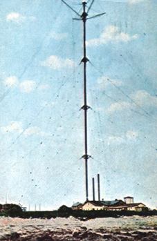
| The Brant Rock, Massachusetts, tower, with the radio shack at the bottom. The tall pipe extending above the transmitter building is the smokestack for the steam engine, which was used (belt drive) to drive the AC generator for Fessenden's synchronous, rotary spark gap telegraphy transmitter and, later, his HF alternator for telegraphy and telephony. (Radioscientist) |
In November 1906, Fessenden and colleagues were conducting experimental transmissions using his newly-developed HF alternator, between stations at Brant Rock and Plymouth, Massachusetts. The station at Brant Rock was modulated by a carbon microphone connected in series with the antenna lead.
About midnight, on an evening early in November, Mr. Stein was telling the operator at Plymouth how to run the dynamo. His voice was heard by Mr. Armor at the Macrihanish, Scotland station with such clarity that there was no doubt about the speaker, and the station log book confirmed the report.
Fessenden's greatest triumph was soon to come. On 24 December, 1906, Fessenden and his assistants presented the world's first radio broadcast. The transmission included a speech by Fessenden and selected music for Christmas. Fessenden played Handel's Largo on the violin. That first broadcast, from his transmitter at Brant Rock, MA, was heard by radio operators on board US Navy and United Fruit Company ships equipped with Fessenden's radio receivers at various distances over the South and North Atlantic, as far away as the West Indies. The wireless broadcast was repeated on New Year's Eve.
The final days of King Spark
As CW systems were later developed (1905-1915), Marconi sought to use his spark expertise to achieve a semi-continuous timed spark that approximated to a continuous wave. In a sense this was the ultimate Marconi spark transmitter and was used as the international tranmitter at Caernarfon, Wales, for a few years. It was noisy, and a Poulsen arc was held in standby.
Eventually, the Marconi spark transmitter was replaced by a General Electric Co. (Alexanderson) HF alternator. The Fessenden-Marconi competing radio technologies battle was over. Fessenden had won. His CW technology was the way to the future.
The US Navy installed a high-power Fessenden rotary spark transmitter at Arlington, Virginia, in 1913, call sign NAA. This transmitter was subsequently replaced by an HF alternator, which was used for their VLF Fleet Broadcast at 33 kHz until the mid 1950s, but over the years the HF alternator was gradually replaced by vacuum tube transmitters, as are today's transmiters being replaced by solid state transmitters.
The three-element vacuum tube was well-known by 1915 to be capable of regeneration and oscillation. It could therefore generate CW. World War I spurred transmitting-tube development. The rise of CW followed in post-war years.
Radio amateurs contributed to the demise of spark. Using spark and CW superpower, commercial and government stations were working intercontinental distances, yet, as 1921 began, no radio amateur signal from this side of the Atlantic had ever been reported heard in Europe.
The ARRL sponsored one-way transatlantic tests in December 1921, and sent Paul Godley, a well-known amateur and engineer, to England with the latest receiving apparatus. Godley set up a tent on a windswept Scottish beach and, using a Beverage wave antenna and frequencies near 200 metres, he copied nearly 30 American radio amateur signals.
CW stations outnumbered spark stations by almost two to one. CW had won the race. By 1924, spark was forbidden on the new 80, 40, 20, and 5-metre radio amateur bands.
Concluding remarks
Fessenden, a genius and mathematician, was the inventor of radio as we know it today. Marconi finally had to admit that Fessenden was right, when in 1914 the Marconi Company purchased a license to Fessenden's patents from the National Electric Signalling Company (NESCO), which later became the Radio Company of America (RCA).
Fessenden was at home in his laboratory, but out of his element when dealing with the business and political aspects of inventing. He never reaped until late in life any financial reward for his radio inventions, and was compelled to spend much time and energy in litigation.
Disagreement with his partners Given and Walker came to a head at the end of December 1910. While Fessenden was detained at a meeting in Pittsburgh, an attempt was made to shut down operations at Brant Rock and to remove his papers, but the quick-wittedness of his wife and the loyalty of most of his staff circumvented this manoeuvre, but only delayed his ouster from NESCO, which occurred on 8 January 1911.
Fessenden immediately launched litigation, first with NESCO and, subsequently, with GE, Westinghouse and, finally, with RCA, which was only settled fifteen years later when he received an out-of-court settlement for a half-million dollars from the Radio Corporation of America (RCA), which had long since acquired Fessenden's patents. The Queen's University Library Archives holds a Fessenden declaration to the IRS in Washington in which he certifies that he received $500,000, with $200,000 of this sum going to his lawyers.
He certainly never reaped the financial rewards that were due him for his radio inventions, but he had the satisfaction of being proven right. He was indeed the greatest wireless inventor of the age.
To conclude, let me continue briefly in the vein in which I began, viz Fessenden was an inventor who worked in many fields of science.
In addition to the inventions already mentioned, Fessenden gave us the radio pager (he called his device a beeper); he gave us sonar, which he demonstrated could detect icebergs, and his fathometer to measure the depth of water beneath the keel of a ship. He gave us turbo-electric drive to power ships; the first gyrocompass, the loop antenna; radio direction-finding; his pheroscope for submarines; a first TV receiver; ultrasonic methods for cleaning; electrical conduit; carbon tetrachloride; and tracer bullets.
Professor Fessenden was deeply disturbed by the sinking of the ocean liner Titanic on her maiden voyage to New York during the night of 14-15 April 1912. The vessel struck an iceberg just before midnight, and sank within two hours. He considered that the Titanic's iceberg avoidance procedure (clear air vision from the crow's-nest) to be very dangerous and that it should be replaced by a reliable system discovered by himself. Sonic frequency echo sounding could prevent a recurrence. He set his mind to perfecting this technology; later known as Sonar (Sound Navigation And Ranging).
The principle of such a sounder was to send a short-duration burst of sound (frequencies up to 20 kHz) from a transducer located about 3 metres below the surface of the water, of such power that it would travel as far as several kilometres through the water. When this wave came into contact with a solid object, such as an iceberg or the floor of the ocean, an echo was created. By measuring the time taken for the sound waves to travel out and the echo to return, it was possible to determine the distance to the object. During the period 1914 to 1925 Fessenden was granted over thirty patents for inventions using sonic frequencies.22
In September 1914, the USS Miami tested Fessenden's Submarine Electric Oscillator in the North Atlantic. Fessenden demonstrated that indeed he could get distinct echoes from icebergs, as far as 4 kilometres from a very large iceberg. The USS Alywin, in that same year conducting tests in the Boston Harbour, showed that Fessenden's sonic detection device could pick up the signals from a moving submarine from distances as great as 9 kilometres. In an associated test, the captain of one US submarine was able to direct the movements of another submarine several kilometres away by modulating the sonic signal by the Morse dot and dash method.
During US involvement in WWI years, 1917-1918, the USN fastened Fessenden's sonic listening device to the hulls of many troop carriers. By picking up the sounds of submerged submarines, the transports could often escape torpedo attacks. Submarines lying silent on the ocean floor could also be detected using his echo sounder.
In the 1920s, Fessenden's depth sounder or fathometer became a common instrument aboard vessels of all sizes from large passenger liners to small fishing boats. It was used on cable-lying vessels. Fessenden set to work to see if his echo sounder could be used as a geophysical tool to detect underground ore and oil deposits. This work led to his development of a new more efficient transducer, a piezoelectric sonar transducer. Not only was the device able to transfer more sound energy to conducting media, sea water or land, but the same device could be used for receiving. "Sound" frequencies as high as 60 kHz could be used.
His work involved with safety at sea won him the Scientific American Gold Medal in 1929. Other awards included the Medal of Honour of the Institute of Radio Engineers for his efforts in that field, and the John Scott Medal of the City of Philadelphia for his invention of continuous wave reception.
Reginald Aubrey Fessenden died in his house by the sea in Bermuda on 22 July, 1932. Burial was in St. Mark's Church cemetery, and over the vault was erected a memorial with fluted columns. On the stone lintel across the top were inscribed the words:
His mind illuminated the past
And the future
And wrought greatly
For the Present
Beneath the scribed words, in the picture-writing of the ancient Egyptians was
I am yesterday and I know tomorrow.
His son summarized his greatest achievements in one sentence: "By his genius, distant lands converse and men sail unafraid upon the deep."
During his brief tenure as principalship of the Whitney Institute in Bermuda, Fessenden met his future wife, Helen May Trott, in 1885. They were married in 1890 in New York City.
Helen must certainly have provided support for her husband in his work, and she must have had a considerable knowledge about his accomplishments. After his death she wrote the book Fessenden: Builder of Tomorrows22, and she must clearly have been responsible for seeing to the granting of seven patents after Fessenden's death. Helen Fessenden died in 1941, and established by her will a Fessenden-Trott Trust, administered by the Bank of Bermuda Limited, Hamilton, Bermuda. This trust, in memory of Professor Fessenden, provides funds for scholarships awarded annually to Canadian students, US students from Purdue and Pittsburgh Universities, and Bermudan students and family members studying at Canadian, UK or US universities.
There are no direct descendants of Reginald from his side of the family, but the Fessenden family name is still maintained by descendants from other branches of the family. Fessenden's only son, Reginald Kennelly Fessenden, died in 1944 in a boating accident off the coast of Bermuda. The Trott name is still maintained by descendants living in Bermuda.
Most of Fessenden's inventions are taken for granted as a part of our everyday life, and few know, particularly the general public in his home country Canada, of the Canadian born genius who provided the world with manifold benefits. History, through the effort of a few, will begin to remember Fessenden.
On 3 June, 1990, Brome County Historical Museum and Archives, Knowlton, Quebec opened a small permanent exhibit and unveiled a plaque honouring Reginald Aubrey Fessenden and commemorating the 90th Anniversary of the first transmission of voice by radio on 23 December, 1900. The Wellington County Museum and Archives, Fergus, Ontario, has just recently mounted the first of a series of exhibits entitled "Marks of Distinction - Celebrating the Achievements and Skills of Wellington County Residents." This first exhibit, opened by the Minister of Communications Canada on 5 February 1993, focuses on the life and work of R. A. Fessenden.
The Department of Communications, in collaboration with the Department of Industry, Science and Technology and the Natural Sciences and Engineering Council of Canada, in recognition of the life and heritage of Prof. Fessenden in the fields of radio sciences and communications, has just recently announced an undergraduate and postgraduate scholarship program to encourage students to continue with university studies in this field of science. The first of these scholarships will be awarded in the spring of 1993.
In the past we have lauded Marconi's successes. In the future we should also pay tribute to Reginald Aubrey Fessenden.
That concludes my lecture. Finally, I would like to tell you about a CBC-Shell Oil Company 1979 drama on Fessenden. This drama was one of a series entitled The Winners, and the particular drama was entitled The Forgotten Genius. While the chronological sequence of events is not quite right, the story is factually correct.
The Sounds of a Spark Transmitter So far as I know, no one recorded for posterity the sounds of on-the-air spark signals. Certainly, because of the tremendous variety of gap speeds for synchronous and non-synchronous rotary gaps, electrode shapes and number of electrodes in use, every spark station had its characteristic sound. This characteristic of a spark transmitter was actually an advantage when there were a number of stations on the air. A spark signal was broad, and within the broad bandwidth of the simple receivers used, there could be several stations operating near the same wavelength with overlapping signals. Communications would have been more difficult if all the signals sounded the same. Certainly, many of you who read this article will have seen, heard, and smelled (the smell of ozone) an operating spark transmitter. Just the sound of an old rotary gap transmitter was good for appreciable DX. Certainly, there are operating spark transmitters to be seen and heard, for example, the shipboard wireless transmitter at the Antique Wireless Association's Radio Museum, East Bloomfield, New York or the early radio amateur type non-synchronous rotary gap spark transmitter at Fred Hammond's Radio Museum, Guelph, Ontario. The American Radio Relay League headquarters' Educational Activities Department, Newington, CT has available for borrowing copies of a VHS videotape in which Ed Redington assembles a working spark transmitter piece by piece while describing his boyhood adventures (and misadventures) in spark communications. But have you heard how the received signal sounded? We had not, so we constructed a 5 MHz spark transmitter using an automotive ignition coil for the induction coil to learn how a spark transmitter worked and how it sounded. This transmitter, we admit, is only a small spark transmitter operated under laboratory conditions. We were particularly interested to hear how Fessenden's spark telephony transmitter might have sounded. Recall that, to modulate his transmitter, he inserted a carbon microphone directly in series with the antenna lead. Our spark transmitter was like the one shown earlier, excepting that Lp and Ls were not directly coupled, but instead were link-coupled through a short length of transmission line. The frequency and the output spectrum of the transmitter is determined by the frequency response of the antenna system. Our "antenna" was an L-C-R circuit, with components chosen to simulate a 5 MHz quarter wave monopole. The output frequency spectrum is indeed very broad, megahertz wide. Somewhat surprising is the magnitude of what appears to be, say, a "third harmonic" of the fundamental oscillation frequency. The primary circuit of a spark system will have a wide band spectrum, but I do not see how it can accentuate, say, the third harmonic. Connected to a quarter-wave vertical, yes; but coupled to a simple series resonant circuit, no. So we measured the CW signal amplitude frequency response of our spark system. The response was like that traced out by the spectrum analyzer when the generator source was a spark (not a swept-signal generator). While this does not explain the unexpected resonance, clearly a spark transmitter when connected to a real quarter-wave antenna would radiate on harmonic resonant responses of the antenna system (for a quarterwave vertical on frequencies three, five, seven, etc times the fundamental oscillation frequency). The signal of our spark transmitter sounds terrible on a narrowband communications receiver, but the receiver used for spark transmission reception was broadly tuned, and the recovered audio can be remarkably good, considering the source was initiated by a spark discharge. To make recordings of the signal received, we had to relearn how to set up and "tune" a spark transmitter. The primary and secondary circuits, the "tank" and "antenna" circuits, must not be over-coupled, since this results in a double-peaked, extremely broad amplitude-frequency response. The spark should take place between polished, hemisphere-shaped electrodes, not between pointed electrodes. And the widest gap possible consistent with regular sparking when the key is held down must be used, since otherwise the signal becomes all "mushy." In effect, we "tuned" our transmitter by gradually narrowing the gap for the best received sound before making a recording at a particular spark rate. Thus, the signals heard and recorded using our spark transmitter were the best that could be realized. We did, however, demonstrate how the spark signal can change from a clear musical sound to a mushy unpleasant sound by using a gap too narrow. We can attest to Fessenden's difficulty with operating, and modulating, a spark transmitter operating at 10,000 sparks per second for spark telephony. The gap adjustment is very critical. When just the right width, the spark is sharply confined, the spark rate regular, the speech loudest, and the disagreeable noise least. Besides the problem with the disagreeable noise, the voice-induced resistance change, which modulated the antenna current via a carbon microphone inserted in series with the antenna lead, is indeed small. One had therefore to shout very loud. However, the signal sounded like Fessenden described it: The words were perfectly clear, except that they were accompanied by an extremely loud disagreeable sound. If you would like to have a copy of recordings made with our spark transmitter, illustrating: spark transmission using a mechanical interrupter, and simulated synchronous rotary spark gap transmissions for telegraphy; and spark transmissions for telephony, write to the author and send $10 to cover the cost of the audio-cassette and handling and mailing.
Relative averaged output specturm for the author's 5 MHz spark transmitter (spark rate 750 sparks/second). Notice the response that appears to be a "hird harmonic" of the fundamental osciallation frequency. (Radioscientist) |
References and bibliography
| John S. "Jack" Belrose
received his BASC and MASC degrees in Electrical Engineering from the University of
British Columbia, Vancouver, in 1950 and 1952, and his PhD degree in Radio Physics from
Cambridge University, England in 1958. From 1957 to present he has been with the
Communications Research Centre (formerly Defence Research Telecommunications
Establishment), Ottawa, where currently he is Director of Radio Sciences. He has written many papers, lectures and chapters in several books, published in various professional publications and journals, and radio amateur magazines on topics of interest and personal research in the field of antennas and propagation. particularly, on HF and VLF antennas by modelling and measurement, VLF and LF radio propagation, and HF propagation in the high-latitude region. During his student and professional career he has been a member a several scientific and professional organizations. Currently he is a member of The Radio Club of America; he is the Canadian National Coordinator of the AGARD (Advisory Group for Aerospace Research Development) Electromagnetic Propagation Panel; a special rapporteur on VLF and LF propagation for CCIR Study Group 6 and he is a Technical Adviser of the ARRL. He has been a licensed radio amateur since 1949. His present call sign is VE2CV, which he has held since 1961. Jack is married to Denise, nee Fenal, formerly of Paris. They have resided at their present address since 1959, have two sons, a married daughter and one grand-daughter. Camping, swimming, cross-country skiing, putting up and taking down antennas, and walking his dog everyday, 25 years of walking an Irish Setter, keeps him physically fit. |
Reprinted courtesy of John S. Belrose, Communications Research Centre Canada