Home » Power Electronics » Flywheel Storage Systems
Power Electronics
Flywheels are fast becoming a reality for energy storage with hopes of replacing batteries in spacecraft and later in electric vehicles. Flywheel design involves creating a flywheel out of a lightweight, yet strong composite fiber. This wheel is then levitated on magnetic bearings and spun at speeds exceeding 100,000 rpm. Magnets are imbedded within the flywheel structure that allow the flywheel to act as a rotor of a three-phase brushless DC motor/generator. The use of a stator winding around the flywheel rotor allows for brushless electromagnetic transfer of angular momentum to and from the flywheel. This transfer of angular momentum is the same transfer of energy that occurs electrochemically in a conventional battery. Present research into composite materials show the possibility that flywheel energy storage could approach energy density levels that are ten times that of lead-acid batteries.
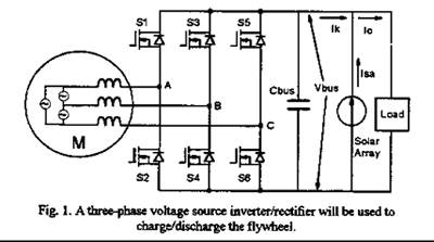
The following schematic shows how power electronics are used in flywheel design. This design uses a three-phase inverter to generate a rotating electromagnetic field. This field rotates around the magnets embedded in the flywheel body and thus tranfers angular momentum to the flywheel, eventually accelerating it. The inverter also operates in a regenerative mode which extracts power from the flywheel, thus slowing it down.

This schematic comes from the report: Development of Power Electronics for a Flywheel Energy Storage System which appeared in the 1995 VPEC seminar procedings. The authors are: Ju Zhang, X. Zhuang, D. Borojevic, and F. C. Lee.