By W.E. Knowles Middleton and Alex Mair
|
. |
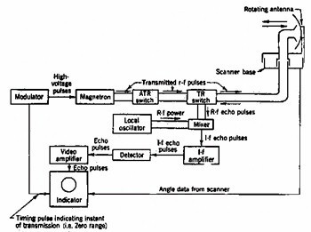
| Figure 1: Components of microwave radar set. (McGraw-Hill) |
The General Principles of Radar
In 1888 Heinrich Hertz showed that the invisible electromagnetic waves radiated by suitable electrical circuits travel with the speed of light, and that they are reflected in a similar way. From time to time in the succeeding decades it was suggested that these properties might be used to detect obstacles to navigation, but the first successful experiments that made use of them were in an entirely different context, namely, to determine the height of the reflecting layers in the upper atmosphere. One of these experiments, that of Tuve and Breit, made use of short repeated pulses of radiation, and this technique was employed in most of the developments of radar.
Electromagnetic radiation travels in empty space at a speed of 2.998 x 10⁸ metres per second, and in air only slightly less rapidly; we can think of its speed as very nearly 300,000 kilometres per second. This speed is denoted by the letter c. Let us suppose that a very short pulse of radiation is directed towards an object at a distance r, and that a small fraction of this is reflected back to the starting point, so that it has traversed the distance 2r. This will take a time t = 2r/c. If we can measure this time we can determine an unknown distance to the target: r = 1/2ct. For useful terrestrial distances t is very small; an object 15 km away, for example, will return a signal in one ten-thousandth of a second.
In practice we need to know more about the target than its distance; we must also determine its direction. This is done by arranging an antenna system to project a suitable radiation pattern that can be rotated in azimuth or elevation. As may be deduced from what follows, a very great deal of ingenuity and engineering skill has been devoted to the design of radar antennas.
This is the place to mention a fundamental fact, namely, that the size of antenna needed to produce a beam of radiation of a given angular width is directly proportional to the wavelength of the radiation, or inversely proportional to its frequency. The first successful radar installations in Great Britain in the years 1935 to 1939 used wavelengths in the 6 to 15 m band, and required very large antennas. Other equipment developed later used wavelengths of 3 m and 1.5 m; and in 1940 the invention of a new form of generator, the cavity magnetron, at once made it practicable to employ wavelengths of 10 cm and even less. Nearly all the radar development at the National Research Council in 1942 and later was done at centimetre wavelengths, universally referred to as microwaves.
| . | 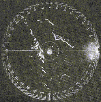 |
| Figure 2: A PPI display. (NRC) |
Let us now consider in a very general way the components of a radar apparatus. These comprise a powerful high-frequency oscillator, a modulator to cause it to emit pulses, and a transmitting antenna, as well as a receiving antenna and a sensitive receiver, the output of which is applied to a cathode-ray tube in the manner familiar to those acquainted with television technique. Rather early in the development of radar it was found preferable to use the same antenna for both transmitting and receiving. This is possible because the transmitted pulse of radiation is very short compared with the interval between pulses, so that the antenna can be disconnected from the transmitter during this interval, and connected to the receiving equipment. To illustrate the components of a wartime microwave radar using a common rotating antenna, Figure 1 is presented. The TR switch disconnects the receiver during the pulses, protecting it from damage, and the ATR switch ensures that the quiescent transmitter does not short-circuit the receiver during the intervening periods. The four blocks designated "local oscillator", "mixer", "I-f amplifier", and "detector" together form the essential parts of the familiar superheterodyne receiver. The radar illustrated in this diagram would display the range and direction on a plan position indicator or PPI, in which the cathode-ray tube displays a circular section of a map with the radar station at the centre. From this centre an outward range sweep is rotated in synchronism with the rotation of the antenna. A target will be shown as a bright spot as the sweep passes it. If the cathode ray tube is provided with a phosphor that continues to emit light for more than the period of rotation of the sweep, a more or less continuous display will result, so that all targets within range will appear as on a map (Figure 2). Other types of display are also used.
While the principles of radar appear to be simple, the actual realization of a workable system calls for technical ability of a high order. In the first place the reflected energy received from a target such as an aircraft at a distance of some tens of kilometres may be only 10-18 of that radiated, so that the transmitter has to be very powerful and the receiver extremely sensitive. In the second place the entire apparatus must be rugged enough to resist weather, transport, and rough handling. The fact that very effective apparatus was produced so quickly under wartime constraints demonstrates a remarkable competence in electrical and mechanical engineering, and a no less remarkable dedication to the common cause.
 |
. |
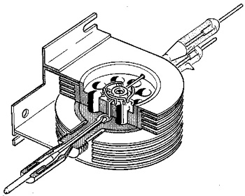
| Diagram of the cavity magnetron. (NRC) |
The Cavity Magnetron
Perhaps the most significant British contribution to radar was the development of the cavity magnetron. This device, pictured left, created high power (10 to 50 kW peak power) high frequency electromagnetic pulses that facilitated the production of more accurate and compact radar designs. Systems capable of being mounted in aircraft became possible. The higher frequencies, and so shorter wavelengths, enabled smaller antenna beamwidths. This increased detection accuracy.
The device was developed by J.T. Randall and H.A.H. Boot working at the University of Birmingham under Professor Mark Oliphant. It was one of the pieces of secret technology brought to Canada as part of the Tizard mission. As early as February 1941, the Northern Electric Company (now Nortel) produced magnetrons for radar sets manufactured on this side of the Atlantic, which was a major achievement considering no one in Canada had any knowledge of magnetrons until September 1940. Today, the cavity magnetron is far from secret. It is the key component of the microwave oven.
The Tizard Mission
In the summer of 1940, it became apparent to Britain that it would need North American research, development and production help in support of the war effort. Sir Henry Tizard was given the very important commission of bringing key British technology to Canada and the U.S., and to petition the two countries for their support.
Besides a great deal of practical operational experience, the Tizard Mission brought at least two key pieces of technology to Canada: the cavity magnetron and the basic plans for a gun-laying, antiaircraft radar system. The NRC took the gun laying plans and developed the GL IIIC. The GL IIIC was one of the first mass-produced radar systems built by Research Enterprises Limited. Though the Canadian built version did not see action in Britain, it was installed in Australia, South Africa, Russia and Canada. The GL IIIC is probably not so important for its contribution to the war effort, but more so for solidifying the equipment production role of Research Enterprises Limited and pushing the envelope of electronic parts design and production in Canada. Many of the British vacuum tube designs required in the GL IIIC, and the cavity magnetron itself, had to be redesigned and manufactured using Canadian resources and production lines.
The Tizard Mission is also important because it seeded the establishment of the Radiation Laboratory at the Massachusetts Institute of Technology. During the war there was much cooperation between the U.S. and Canada in developing microwave technology for radar and other applications, and the NRC sent personnel to the M.I.T. Radiation Laboratory. See Fred Heath and the Invention that Changed the World for the story of but one of many Canadians who contributed to the developments at M.I.T.
The Role of the NRC
The Radio Branch of the National Research Council (NRC) was the focal point of Canada’s contribution to the development of radar technology during World War II. It grew from about 12 personnel in 1939 to more than 300 by 1945, and was aided by Canadian Military Services personnel, as well as the Universities of Western Ontario, Toronto, McGill, and Queen’s. The Radio Branch developed about 12 types of radar that were put into mass production and about twenty types were produced in small quantities for specific Services requirements.
To support the mass production of the radar sets, the Canadian government created a Crown corporation on the outskirts of Toronto called Research Enterprises Limited (R.E.L), which stayed in business until September 1946. The idea for R.E.L was first conceived by General A. McNaughton, to supply military optics, which he found to be in short supply during the First World War. But soon after the development of radar sets began at the NRC, a strategic mass-producer of the equipment would be needed and the wartime role of R.E.L. was established. During the war, more than 8300 radar sets were produced at R.E.L. for the Canadian, U.S. and British Forces. Most of these sets were either production versions of NRC designs, or adaptations of British designs to North American components and practices.
Reprinted courtesy of National Research Council of Canada and the University of Alberta