 |
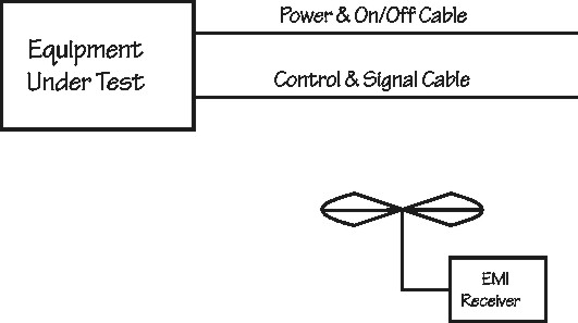
Figure 1: Radiated Emissions (RE02) Tests |
by Elya B. Joffe
K.T.M. Project Engineering
This is a true story!
Once upon a time, there was a high performance airborne data-communication system, required to meet strict emission and susceptibility requirements of MIL-STD-461C.
In the EMC tests (Figure 1), excessive emissions (+10dB) were identified in the RE02 (E-Field radiated emissions) at approximately 30MHz.
|
Figure 1: Radiated Emissions (RE02) Tests |
Aaaargh! Failure!!! That was totally unacceptable.
In the conducted emission tests, similar excessive emissions at 30MHz were found on the CE03 (Conducted Emission) tests (see Figure 2). OK. So solving our problem was "a piece of cake", isn't that right? Just fix the emissions on the 115VAC 3 phase lines, and we're done. Right?
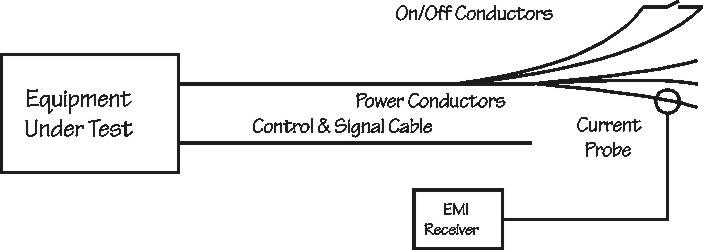 |
Figure 2: Conducted Emissions (CE03) Test on Phase Lines (note the long overlapping phase and on/off lines) |
Wrong!!!
The power supply was tested as a separate LRU (line replaceable unit) by the manufacturer, and fully complied with the CE03 test limits! So, the problem is not from the power supply (or so we assumed... Oh, but in EMC, never assume anything!)
Where do we begin?
Since the conducted emissions were not identified in the power supply, as a stand-alone unit, we considered a possible resonance in the power line filter, excited by some noise near 30MHz. Particularly, possible interactions in the multi-point grounding topology of the system could generate such loops. Since the LRU's external power connector was wired by a high-performance shielded cable directly (and not via the motherboard) to the power supply's power-input connector, possible ground loops could be generated. So, we "cannibalized" the shielded cable's shield, "opening" a possible "ground loop" and... and guess what? NOTHING! The problem was still there. Well, actually, no one really believed it was a ground loop...
So, hi-ho, hi-ho, back to the bench we go! Since we saw that the conducted emissions and radiated emissions were (expectedly) correlated, we decided to continue with conducted emission (CE) tests only at that time, believing that if we solved the CE problem – we'll be OK with radiated emission (RE) too. Not so simple, apparently!
At this stage it was quite evident that the power supply was compliant, but Đ it may have been tested using resistive loads, not dynamic loads. That could have explained coupling of noise emissions from the load circuits via the power supply to the output leads (with insufficient or inadequate filtering at those high filters, EMI from the circuits could have leaked through the power supply). Naturally that could be identified in a stand-alone power supply test, we thought. So we removed all the load circuits from the system (the System Controller (CPU) card, the I/O card, the Video Display card, and the Transceiver card). Thus the entire "system" under test was reduced to the power supply and the motherboard only. Shouldn't it comply now? Sure as hell it... DID NOT! Of course – nothing is simple in EMI!
Now what? No! It could not be the Motherboard... Nothing else was connected to it, and it was totally passive.
"No other way – the problem must be within the power supply!", we thought. But we could not tell why...?
So, we did the only reasonable thing at this time – when the test fails – check the set-up!
Actually, we called the power supply manufacturer, and checked the set-up HE used during his tests. And Eureka! The set-up was not the same! In fact – it was significantly different. The "On/Off" control line and return (2-wire line) were very short, and the 3-Phase power lines were routed separately along their entire length (see Figure 3). In our cable, the power lines were run together with the "On/Off" wire pair, and were 2.5 meters long! It looked like we were getting on track!
So – first of all, we separated the "On/Off" lines from the power lines (see Figure 4). Having done that, and having repeated the CE tests, the conducted emissions (on the 3-phase power lines) were significantly reduced (but not eliminated)... OK, now what?
It looked like what we had here was a case of conducted emissions on "innocent" passive control lines (Open/Ground logic). Those emissions were apparently coupling to the power lines (see Figure 3). Separating the "On/Off" lines from the phase lines reduced crosstalk between them, thus conducted emissions were reduced.
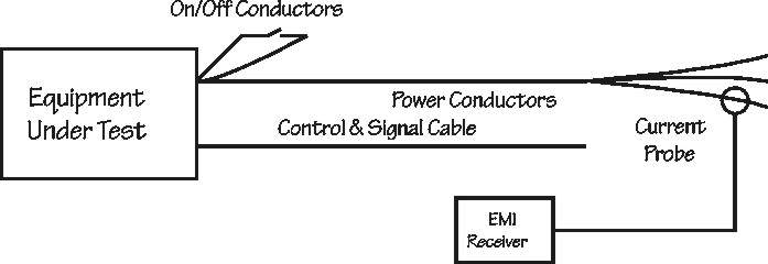 |
Figure 3: Conducted Emissions (CE03) Test on Phase Lines Đ Power Supply ManufacturerŐs Setup (note short On/Off lines) |
So this is a complex "crime": Conducted emissions and Crosstalk. Wasn't that enough?
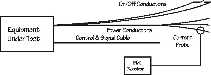 |
Figure 4: Conducted Emissions (CE03) Test on Phase Lines Đ On-Off Lines separated |
Well, then - how could we prove that the "On/Off" line was the culprit? Easy! We shortened the "On/Off" line to 2" and short-circuited the lines, providing the "On" command to the power supply but also reduced the current loop size (see Figure 5). Wow! Conducted emissions on the phase lines were down... We WERE on track! We thought we knew the emission source – the "On/Off" wire pair. But – was the problem solved? Not so quickly...!
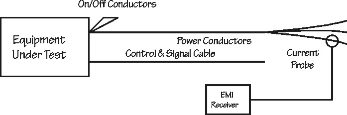 |
Figure 5: Conducted Emissions (CE03) Test on Phase Lines with Shorted On/Off lines |
We reinserted all the load circuits, and repeated the conducted (CE03) and radiated tests (RE02). GREAT! Low emissions!
Encouraged by the results, we reconnected the long "On/Off" wire pair, and maintained the separation between them to the phase lines. However, we maintained the short circuit ("On" command) close to the EUT (see Figure 6). As expected (sure!), emissions were increased. Why "sure!"?
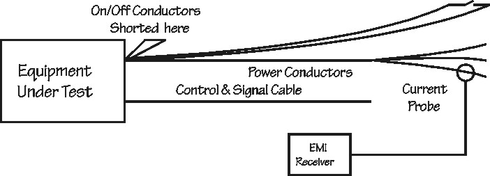 |
Figure 6: Conducted Emissions (CE03) Test on Phase Lines with Long On/Off Conductors Shorted near Connector |
The explanation was actually quite simple. At the frequency of 30MHz, emissions are typically common mode, so even if we short-circuited the "On/Off" lines near the EUT, still common mode currents could and would flow on the longer lines...
We decided, therefore, to apply the "emergency room" approach, and do some "research and diagnostics": We conducted CE03 tests, with the current probe placed on both lines of the wire pair (see Figure 7). Naturally, we got emissions! BINGO!
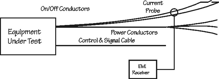 |
Figure 7: Conducted Emissions (CE03) Test on Both On/Off Conductors (Measuring Common Mode Emissions) |
Of course – it was a case of common mode conducted emissions! We tried a ferrite bead on both lines (in a common mode choke configuration), but – it did not work! Surely a small capacitor between each of the "On/Off" lines to the chassis (CM capacitors) of the enclosure would do (or so we thought). So, we stuck there whatever caps we had, 30nF, I believe (see Figure 8). Emissions were... still there!
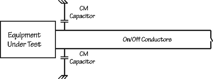 |
Figure 8: Line to Chassis (CM) Capacitors installed on both On/Off Lines (note that power lines are in place but not shown in the figure for clarity) |
Oh, boy! What now? Apparently the power supply did not know that at this frequency emissions are typically common mode...
So, we repeated the CE03 tests, on each of the "On/Off" lines separately. Of course, the emissions were still there, even with the caps.
So, next - we played the well known trick: We twisted one of the lines through the current probe, in practice – reversing the direction of the common mode current on one of the lines through the probe and we routed the other wire straight through it (see Figure 9). Here we are – we still got non-zero (in fact – significant) levels of emission on both lines! So there was also a differential current emission component!
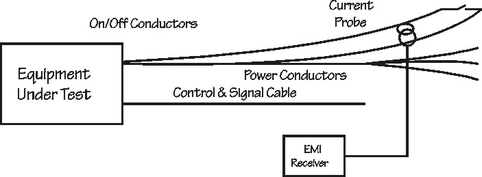 |
Figure 9: Conducted Emissions (CE03) Test on Both On/Off Conductors (Measuring Differential Mode Emissions) |
Now, it was easy – we added an 80nF capacitor (that's what we had) between the "On/Off" line and it's return (line to line) (see Figure 10). The problem was solved!
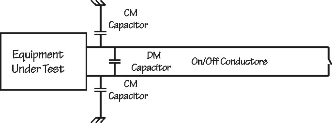 |
Figure 10: Line to Chassis (CM) and Line to Line (DM) Capacitors installed on On/Off Lines (note that power lines are in place but not shown in the figure for clarity) |
We went back (with drawn swords) to the power supply manufacturer, and queried his design. Why wasn't that line filtered?
Apparently – it was, but with a common mode choke, only. Since it was a passive and optically isolated line, the manufacturer assumed that capacitors were unnecessary...
Naturally, the power supply had to be retrofitted, and a miniature capacitor circuit was added to the power supply "On/Off" lines input leads. Now we had A COMPLIANT POWER SUPPLY WITH A COMPLIANT CONTROL. Oh – what was the source of the emissions?
It is believed to be due to a resonance generated internally to the power supply power line filter, which could be expected since no damping resistors could have been added without degrading other performance characteristics of the power supply (heating, efficiency, etc.). Such a resonance would also explain why the interference appeared as a combination of both common mode and differential-mode emissions.
The problem was solved after 3 full days and sleepless nights of work, about 50 spectral plots, and many, many cups of coffee. In the final analysis - three small capacitors did the job!
This was a complex EMC problem, although not really complicated:
By the way, after modification, the RE02 tests passed successfully, with flashing colors, having corrected the problem.
We called this case – the "Twist and Shout" problem (the more "twists" it had, the more our bosses shouted at us...)
 |
Elya B. Joffe can be
contacted at
1713 Herzl St.,
P.O. Box 264
Kfar-Sava 44102, ISRAEL.
E-mail: eb.joffe@ieee.org
EMC
"Call for War Stories 2001!" This paper was presented at the special "War Stories" session held during the 2000 IEEE International Symposium on EMC in Washington, DC. Several EMC engineers submitted papers for presentation at this session, while several more EMC engineers who attended the session verbally shared similar "War Stories" following the session. It was a lively, informative and very interactive session - not to mention being educational and entertaining, too. Many thanks are due to those who participated.
Encouraged by the paper submittals and attendance at this inaugural session, organizer Tom Chesworth of Seven Mountains Scientific is seeking material now from authors for a repeat "War Stories" special session at the 2001 IEEE International Symposium on EMC in Montreal. If you would like to submit a "War Story" along the lines of this paper, please contact Tom at 814-466-6559 or tom@7ms.com .