Many EMC professionals, myself included, have
been involved with downsizing, layoffs, or whatever term is currently
in use. The end result is that many people have to refocus or
recycle their careers.
IEEE-USA has created the Professional Activities Committee for
Engineers (PACE) network to promote the professional interests
of their members. A primary focus is helping members to match
their skills to the current job market. I was appointed to be
the EMCS PACE Coordinator because of my years of EMC experience
and my own change in career direction. My new career path is in
the Wireless Communications Section of a small, privately owned
engineering company.
While working on improving the adjustment efficiency of a five-channel
VHF base station, I developed the following technical application.
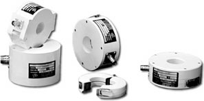
Most EMC experienced personnel are very familiar with clamp-on
broadband RF current probes that are sold by several manufacturers.
Different models are available covering different frequency ranges
and aperture sizes.
A design requirement was to verify and adjust the power output
of each transmitter in a combined five-transmitter VHF system.
Typical operation was to operate the control channel transmitter
at the licensed Effective Radiated Power (ERP). Other transmitters
were then adjusted to be three decibels (dB’s) below the
control channel.
The existing recommended procedure was to insert a wattmeter in
cable N and to set the power output of the control transmitter,
TX5 to the licensed ERP. Verification of the band pass filters
(F) and isolator (ISO) attenuation required the following steps:
-
Insert the wattmeter into one of the cables
-
Tune the applicable transmitter
-
Record the information
-
Disconnect and move the wattmeter to another
cable
-
Analyze the data
This procedure was very labor intensive and
also susceptible to connector damage. It was modified to utilize
a clamp-on broadband current probe. The selected probe was an
A.H. Systems model BCP-512 with a frequency range of 1 MHz to
1000 MHz to cover the VHF frequency used. The probe output was
connected to a suitable spectrum analyzer. This configuration
allows the rapid adjustment of the other four transmitters to
3 dB below the control transmitter level.
Using a clamp-on probe provided several additional benefits. Clamping
on to the transmitter output coax lines (A-E) allowed the spectral
analysis of each transmitter; moving the probe to the filter output
lines (F-J) allowed the verification of the manual tuning of the
band pass filters (F1-F5); and finally, moving the probe to the
isolator output lines allowed the verification of the listed attenuation
of each isolator.
The application of a proven EMC technique greatly improved the
communications base station measurement and verification. Additionally,
multiple coaxial cable disconnects were reduced to only one, thus
cutting short the time required and forestalling possible connector
damage. The most interesting part of this test was that I could
find no references describing the use of current probes in communication
applications.
Other EMC procedures may be applicable for use in other technical
areas such as building construction and power design. Please send
me information of other EMC techniques that have been “recycled”
to new uses to boost efficiency and innovation in a new area.
I can then share the information with others who are now in a
new non-EMC career. EMC
Bill McGinnis is a Senior RF Designer with Alexander Utility
Engineering, Inc. where he designs and deploys various communications
and SCADA RF systems. He has over four decades of civilian and
military EMC experience. Professional activities include IEEE
membership, with six years elected to the EMCS BOD, EMCABS editor,
and currently the EMCS PACE Coordinator. He may be reached at
wmcginnis@ieee.org
|
|
|
 Recycling
People and Techniques
Recycling
People and Techniques