By Andrew Drozd,
Subcommittee Co-Chair on Experiment Demonstrations
with Contributions by Larry Cohen
When I originally set out to prepare this article, I intended to write strictly about the Special Session demonstrations held at the Colorado Convention Center in Denver last August as part of the highly-successful 1998 IEEE International Symposium on EMC. As I began to write, I realized we had come a long way since Anaheim in 1992, the year we had seriously discussed launching this format as part of future IEEE EMC Society symposia. In retrospect, we experienced some growing pains, learned a great deal, accomplished much, and had some fun along the way. In this article then, I decided to cover a little history, a lot of perspective, highlight some of the added dimension that this session brings to our technical conferences, and provide a glimpse towards Seattle in 1999. I’ll also indulge in some deserved name dropping, if you’ll permit me.
Let’s begin with a few perspectives. First, many of you may have noticed I was on hiatus doing other things for the past two years on behalf of the EMC Society and for my day job. In the meantime, I relinquished the responsibilities of Special Session Subcommittee Chair to Larry Cohen who readily and ably took charge, and did an excellent job to boot. Thanks Larry and the rest of the subcommittee for your continuing hard work and sacrifices!
Unfortunately, we were still amidst somewhat of an identity crisis. Something needed to be done about enhancing our visibility and defining our session’s educational “spin” as part of the symposium program. Last year I decided to join forces with Larry for Denver to help achieve these goals.
I am elated to say we were successful in achieving our goals. The Special Session on EMC Experiment Demonstrations held in Denver last August was a tremendous success, in more ways than one! It was indeed an educational experience and something of a milestone considering the event’s brief history.
Judging from the heavy traffic and the positive feedback from attendees in Denver, I think we definitely hit stride. This year’s session was also a model to be followed for future symposia, but more on that later.
This was the sixth consecutive year that the Special Session was held under the sponsorship of the EMC Society Education Committee. This is an important milestone for several reasons. First, it is still a relatively-new format whose original purpose was not completely understood and as I said above, suffered something of an identity crisis at the beginning. We weren’t sure at first if this was to be treated as an exhibit, a spin-off of the traditional technical paper sessions, or if it was to be something completely different.
I believe we have finally established something unique with the primary aim being EMC education, a goal which is in step with one of President Hoolihan’s visions for promoting education throughout the EMC Society during his term. I believe the session has been achieving its fundamental EMC education goal while adding a “new dimension” to the tried and true symposium format. Credit is given to the founding fathers for their original vision. Much of the inspiration for this session is due to the ideas of Clayton Paul, Kimball Williams, Dick Ford, Henry Ott, and other veteran EMC Society members.
The session format has been embraced more widely each year as evidenced by the number of people who volunteer experiments and by the ever-growing attendance. This format provides a nice balance to the regular paper sessions, workshops, and exhibits. The session combines the features of an open-forum-type paper session, a hardware exhibit, and the dynamics of a workshop. The symposium committees have begun to recognize the importance of this session and our objectives, and have been giving the session the attention and visibility it deserves. This was especially evident in Denver as many of you who attended know.
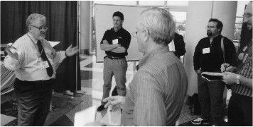
For those unfamiliar with how this session is run, we arrange each year as part of the symposium to have available some of the most internationally recognized movers and shakers in the EMC community representing industry, government, and academia. Their challenge is to demonstrate important EMC concepts through a series of interactive experiments run continuously over the three main days of the symposium. The operative word here is ‘interactive’, where onlookers are invited to directly participate in the experiments and ask plenty of questions. I believe this type of “hands-on” involvement is education at its finest. It’s also a fun way to learn and occasionally provides a challenge or two to the presenters.
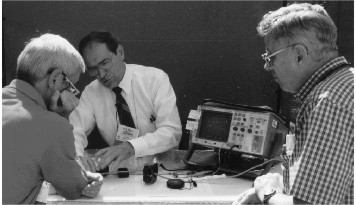
(All photos by Ken Wyatt)
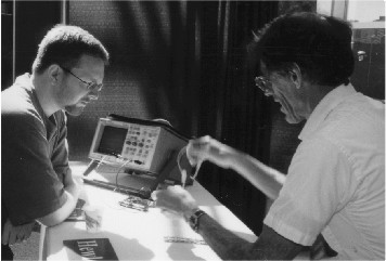
Jack Meyer (c) demonstrates the use of “Ferrites for EMI Control.”
Past presenters by the way, have included: Ted Anderson, Jim Drewniak, Tom Van Doren, Dick Ford, Jasper Goedbloed, Kevin Goldsmith, Lee Hill, Todd Hubing, Mohammed Issa, Ken Javor, Tom Jerse, George Kunkel, Maqsood Mohd, Richard Mohr, Jim Muccioli, Mark Nave, John Norgard, Clayton Paul, Jose Perini, Bill Ritenour, Mike Seifert, Doug Smith, Norm Violette, Mike Violette, Don Weiner, James Whalen, and yours truly. So you can see that there is a wealth of experience, knowledge, and personality that comes into play here each year.
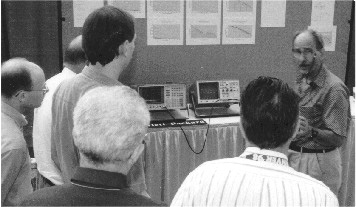
Jim Drewniak (far right) explains an important point during his demonstration on “Transmission Line Effects in PCB Design.”
The experiments demonstrate EMC concepts and principles, phenomena and effects, and measurement methods - some of which invite controversy and debate (this is when it really gets interesting!). Experiments have demonstrated the effects of PC board radiation coupling; component-cable crosstalk; grounding and shielding strategies; spectral analysis techniques using test hardware; effective EMC test methods and practices; how EMC instrumentation is used to measure EMI at the device and component level; and how EMC standards play a vital role in achieving EMC as part of the measurement methodology. Fundamentally, the demonstrations are meant to show how in most cases, fairly simple test equipment and hardware can be used to study or quantify various electromagnetic phenomena and effects. The experiments vary daily and are intended for the journeyman EMC engineer as well as the experienced EMC technologist. EMC education early on in one’s career is one important aspect. Promoting life-long learning is another. In any case, the constant goal of the session is one of educating our community.
Now, a little history and background. The Denver session experiments built upon the previous trials and successes of Dallas (1993), Chicago (1994), Atlanta (1995), Santa Clara (1996), and Austin (1997). Whereas 1993 was the “test drive” year, 1998 was the year we “bought the Cadillac” in terms of the session’s highly-visible venue, technical content, and quality of presentations. Many thanks go to the Denver Symposium Committee (Barry Wallen, Charles Grasso, Bob Reinert, Tony O’Hara, and the rest) for giving us a spacious and attractive location in which to group the experiment stations along with receiving responsive, first-class service. Arranging for the Rocky Mountains as a backdrop was a nice touch.
Since the beginning, the experiments have been largely based on those documented in the Education Committee’s “EMC Experiments Manual”, Volume 1 originally compiled and reviewed by Clayton Paul and Henry Ott. Jim Drewniak of the University of Missouri-Rolla is currently compiling additional experiments for the Education Committee to generate Volume 2 of the manual.
Volume 1 can be downloaded from the web by referencing the URL ftp site address at https://emclab2.ece.umr.edu/files/EMCman.pdf.
This year, we reprised several popular experiments from the manual which were also showcased in previous years, as well as introduced a few new demonstrations. This year’s experiments ran the gamut from measuring a signal’s spectral properties using an oscilloscope and spectrum analyzer, to demonstrating the application of advanced infrared measurement systems for predicting corresponding electromagnetic field intensities, to challenging EMC regulatory standards using a rather novel shielded test fixture. We had a total of eighteen experiments and nineteen presenters. Several of the experiments were repeated over the course of the three days. Here’s a rundown of the Denver demonstrations:
In the experiment titled “Transmission-Line Effects in PCB Design”, Dr. James Drewniak of the University of Missouri-Rolla’s EMC Laboratory illustrated how certain transmission-line effects such as reflection from resistive and reactive discontinuities that included parasitic interconnects, manifest themselves. Signal fan-out and distributed (reflection) versus lumped (ringing) effects were also demonstrated. Methods for developing equivalent circuit models and estimating the values of the parasitic parameters were shown.
Art Light is shown demonstrating “EMI Effects of Spread Spectrum Signals.”
The demonstration “EMI Effects of Spread Spectrum Signals” by Arthur Light of ITT Industries, Alexandria, VA showed the forms of spread spectrum (SS) transmissions and their effects in the electromagnetic environment. The demonstration also showed the apparent reduction of peak power by spreading the energy across a much larger frequency band for direct sequence spread spectrum (DSDD) and for frequency hopping spread spectrum (FHSS) signals.
Additionally, it demonstrated the increased potential for causing interference because of the much higher frequency occupancy. The demonstration then illustrated the differences in the types of interference caused by the two forms of SS transmissions.
In the experiment titled “Demonstrating Parasitics in Passive Components in a Line Impedance Stabilization Network (LISN)”, Dr. James Whalen of the State University of New York at Buffalo showed how a spectrum analyzer and tracking generator were used to measure and display two insertion losses: (1) the insertion loss between the Equipment Under Test (EUT) and the spectrum analyzer used to measure the EUT noise voltage caused by the conducted emission current on the phase line; and (2) the insertion loss between the power grid and the spectrum analyzer used to measure the noise voltage caused by the power grid conducted emission current on the neutral line. Ideally, the former insertion loss should be 0dB which the measurements showed was nearly the case. The measurements indicated that the actual response was far from ideal with noticeable resonances and much lower attenuation characteristics observed. Professor Whalen also showed the results of computer simulations for an ideal LISN without parasitics and for a LISN with parasitics using PSPICE Evaluation Version 7.0. Some, but not all, of the observed behavior could be accounted for in the simulation. Dr. Whalen invited those who witnessed the demonstration and who have suggestions regarding the differences to email him at jjw@eng.buffalo.edu.
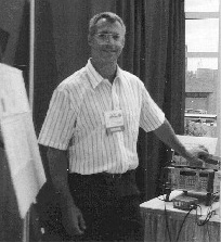
Ken Javor enjoys a break during his demonstration
“Rationale for Changing Conducted Emission Limits”,
or more appropriately titled,
“A Better Way to Control Conducted Emissions?”
In “Barkhausen Effects”, Dr. Theodore R. Anderson of the Naval Undersea Warfare Center Division Newport gave an experimental demonstration of this so-called effect by enabling the observer to actually hear the clicks produced by microscopic magnetic domain realignment from a loudspeaker. The Barkhausen EMI noise comes from sudden domain realignments brought about by an externally-changing magnetic field which cause inductive “kicks” in a coil connected to an amplifier and loudspeaker. Controlling Barkhausen noise is important for reducing noise in magnetic heads.
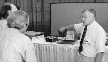
It’s standing room only near Bill
Ritenour’s demonstration on “Testing for Compliance to EN61000-4-2 (1995 -
ESD)”.
Bill is shown on the far left.
The experiment “Surge Effects and Transient Suppression Techniques” demonstrated by Dr. J. L. Norman Violette of Voilette Engineering Corporation and Mike Violette reviewed surge phenomena and protection techniques. Lightning and AC power load anomalies create destructive surge energies that can harm equipment, if not properly protected. Several examples of surge coupling and prediction were presented, along with a live demonstration of the effects of surge energies on typical components (ka-boom! per the presenters). Protection techniques were demonstrated that included MOVs, filters, and hybrid suppressor arrangements.
In “Current Probe Demonstrations Including Phase Measurements”, Doug C. Smith of Auspex Systems in Santa Clara, CA demonstrated both how current probes work and some interesting uses for them. One experiment showed how to extend the flat portion of a probe’s frequency response to lower frequencies by terminating the probe with a lower resistance than for which it was designed. Other experiments showed relative phase measurements using a pair of matched probes.
“Ferrites for EMI Control” by Jack Meyer of Anteon Corporation in Fairfax, VA showed a simple method of measuring EMI voltages and currents inside an EUT.
Also shown were the advantages and potential problems of using ferrites to reduce conducted EMI problems. The test setup used a 2 MHz RF signal generator as a source of simulated EMI on a cable going through the EUT to a ground on the other side. An oscilloscope connected to a current probe and a high pass voltage probe were used to measure the resulting RF current and voltage inside the EUT. In one part of the demonstration, two physically identical, but electrically different ferrites were placed between the source and the EUT to show the difference in reduction of EMI current and voltage inside the EUT, resulting from the frequency responses of the two different types of ferrite materials. In the second part of the demonstration, a ferrite was placed between the EUT and the point where the cable was grounded.
To the surprise of many, the current inside the EUT decreased just as before, but the voltage increased. The reason for this is that the increased impedance to ground caused more voltage to drop across the ferrite. One of Jack’s closing statements was that if one puts a ferrite on a cable and the EMI at the EUT worsens, then it probably means that the ferrite was placed on the ground side of the EUT, rather than on the source side, and that the EMI problem inside the EUT is caused by high impedance or voltage coupling rather than by magnetic field or current coupling.
Doug Smith (R) reviews the finer points during “Current Probe Demonstrations Including Phase Measurements.”
In “ESD Effects on Timing Circuits”, Ahmad M. Fallah of Phoenix International Inc. and Dr. Bob Nelson of North Dakota State University in Fargo, ND examined the effect of ESD on a timing circuit. In the first case, an unprotected timing circuit was subjected to an ESD event. The performance and recovery of the circuit from the stresses caused by the ESD were then investigated. Next, a number of ESD countermeasures were added to the circuit to prevent and/or minimize the effect of the overstress on the circuit. In each case, the performance and recovery of the circuit was re-evaluated, thus illustrating the beneficial effects of using various ESD protection devices.
The experiment “Clock Separation as a Method of EMI Reduction” by Donald R. Bush of dBi Corporation in Winchester, KY showed that by slightly varying clock frequencies, one can reduce emissions from a product by 6 or more dB. If the clocks are varied by an amount that exceeds the receiver bandwidth of the measurement instrument, this will usually be the case.
In “ Demonstration of Magnetic Field Shielding Techniques”, Dr. Tom Van Doren of the University of Missouri-Rolla’s EMC Laboratory explained and demonstrated the following shielding techniques: (1) self shielding produced by the signal current location, as in a twisted pair; (2) flux shunting using a high-permeability magnetic material; and (3) generating an opposing flux using induced eddy currents.
In “Rationale for Changing Conducted Emission Limits” or more appropriately titled “A Better Way to Control Conducted Emissions?”, Ken Javor of EMC Compliance in Huntsville, AL demonstrated that radios (the victim protected by conducted emissions limits) are much more sensitive to common mode than to differential mode noise. Present practice is to measure vector sums and differences of these two noise types at each LISN port, and impose the same limit, regardless of noise type. Ken’s experiment demonstrated a technique for separating the different modes, and showed that a limit for differential mode noise can be relaxed 20 dB from the limit for common mode noise.
Incidentally, Ken will be publishing an article on this subject which is anticipated for the Winter edition of the newsletter. Look for it as Ken’s findings have significant implications to current industry product EMC compliance issues.
In “Crosstalk Between Parallel Current Loops”, Pierre Beeckman of Philips Research Laboratories in Eindhoven, The Netherlands demonstrated an original experiment documented in a book on EMC written by our friend and colleague, Jasper Goedbloed. This experiment demonstrated that crosstalk between parallel current loops is a consequence of both the electric and magnetic field coupling between these loops. The experiment also demonstrated that: the load conditions in the loops determine the electric and magnetic field contributions to the crosstalk; near-end crosstalk effects, i.e. only crosstalk at the end near to the generator occurs when the loops are terminated in their characteristic impedance; the amount of crosstalk depends on the distance between the parallel loops, and may be reduced by an intermediate loop; unwanted resonance effects may occur when the electrical length of the intermediate loop is a fraction of the wavelength of the applied signal; and that grounding of a screen (shield) at only one end may lead to an increase in crosstalk.
The experiment “A Demonstration of How Electrostatic Discharge is Generated”
by Dr. Maqsood Mohd of Sverdrup Technology at Eglin AFB, FL focused on the concepts of
electrostatic materials and their charge development. The demonstration used a capacitor
technique to store the charge and allow it to discharge through the air. The charge is
developed sufficiently high to breakdown the air at a small area of a conductor. Finally,
the experiment demonstrated the relationship between the accumulated charge and the area
of accumulation for discharge to occur.
T. J. (Bill) Ritenour of EMC Compliance LLC in Boulder CO, demonstrated “Testing for
Compliance to EN61000- 4-2 [1995] (ESD).” Bill showed what equipment is needed to
conduct this test and how it is used in the measurement procedure to verify compliance to
the specified limits.
John Norgard of the University of Colorado at Colorado Springs demonstrated two separate
experiments titled “Parasitic Effects in Circuit Elements” (based on an
experiment originally devised by Clayton Paul) and “Infrared Images of
Electromagnetic Fields (Aperture Coupling into a Cylinder)”. The former demonstrated
how the filtering effectiveness of capacitors can dramatically change as a function of
lead lengths due to parasitic behavior at high frequencies. The latter experiment
(developed in conjunction with Michael Seifert of the Air Force Research Laboratory, Rome
Site) demonstrated an advanced test technique and fixture which establishes a relationship
between infrared measured quantities and corresponding electromagnetic field intensities.
In “Spectrum of Non-Sinusoidal Signals,” Dr. Jose Perini, professor emeritus of Syracuse University NY, demonstrated how changing waveform parameters such as duty cycle, pulsewidth, and risetime can drastically affect a signal’s frequency spectrum. In this demonstration, a spectrum analyzer was used to display the spectra of several different non-sinusoidal waveforms. Displayed results were compared with computed results. The non-sinusoidal signals studied were: rectangular pulse, trapezoidal pulse, an AM modulated signal, and a phase (or frequency) modulated signal. It was shown that the rectangular pulse has a sinx/x spectral form. It was shown that by varying the duty cycle to 1/2, all the even harmonics are zero. For a duty cycle of 1/3, every third harmonic is zero, and so on. For the trapezoidal pulse with the same rise and fall times, the 20 dB/octave and 40 dB/octave breakpoints were shown. In the case of the AM modulated signal, both sidebands appeared and changed in amplitude as a function of the modulation index. For the phase (or frequency) modulated signal, the equation for the sidebands was shown along with a plot of the Bessel functions. It was shown that by changing the frequency deviation, the carrier signal completely disappears at the zeros of Jo (deviation). By changing the modulation frequency it is possible to see that the phase modulation signal requires a variable bandwidth.
Randal Vaughn of Motorola in Arlington, IL in conjunction with Lee Hill of Silent Solutions in Hollis, NH demonstrated the experiment “Clock Frequencies, Duty Cycle, and Low Pass Filtering”. This was actually a series of experiments which showed the effect of high-frequency current paths, inductance, and gaps in PCB ground planes; and shield terminations, radiated emissions, common mode-current and pigtails.
Finally, Michael O. Hatfield of the Naval Surface Warfare Center Dahlgren Division demonstrated an experiment using a miniature mode stirred chamber.
The chamber was constructed with a partial screened glass front to allow one to visualize the mode-stirring process. This involved exciting three orthogonally-oriented, six-inch florescent tubes. The “dark bands” that traveled the length of the tubes showed the stirring of the modes. Random polarization was demonstrated when all three orthogonal tubes lit up.
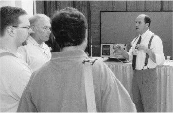
All eyes are on Jose Perini (far right) during his demonstration on “Spectrum of Non-Sinusoidal Signals.”
As I mentioned at the beginning, I considered the level of support and cooperation for this year’s event to be a model for future symposia. The Denver symposium committee clearly appreciated the importance of this session and supported our planning efforts from the very beginning. Our appreciation also goes out to each of the presenters for a job very well done.
We also owe a debt of gratitude to many supporters behind the scenes, in particular, the individuals and companies who worked very hard to get us state-of-the-art test equipment and materials to support the experiments.
These included all of the oscilloscopes, spectrum and network analyzers, function generators, meters and probes, etc. that many of you saw set-up at the experiment stations. I cannot conclude this article without expressing thanks specifically to the following people for their help in getting us the equipment we needed:
Hewlett-Packard:
Jan Brown and Dennis Handlon of Santa Rosa, CA; Ken Wyatt and Barbara Martin of Colorado
Springs, CO; Kevin McMenamin of Baltimore, MD; Merrilee McMurray, Support Administrator,
T&M Consignment Hub.
Tektronix, Rohde & Schwartz, and Advantest:
Mark Klein of Albany, NY; Tabb Warsinske of Denver, CO; Henry Benitez, Cliff Morgan and
Peggy Rogers of Beaverton, OR.
Fluke Corporation
Hilton Hammond and Irene Geyer of Everett, WA.
Because of their efforts, it was a win-win situation overall. We not only gained an appreciation for their equipments’ capabilities, but also saw how the equipment is used to perform EMC-type measurements. I again encourage you to contact these individuals for guidance in the selection of EMC test equipment for your needs. They are a group of true professionals who know their hardware and who are willing to work with you.
This brings me to next year’s Special Session in Seattle and some closing comments. We have already begun planning the session and have a partial list of experiments tentatively lined up. We plan to expand the number of experiments to as many as 26 or so with up to 6 experiments each in the morning and afternoon of the three days. If you have ideas for an experiment and want to have it considered, please feel free to contact Larry Cohen [(202) 404-7726, cohen@radar.nrl.navy.mil] or me [(315) 337-4396, andro1@aol.com] to discuss your ideas. Also, periodically visit the official Seattle 1999 IEEE International Symposium on EMC web site to find out more about the upcoming conference and session agendas. The site will also provide a list of experiment topics being considered. We look forward to your input.
Thanks for your time! Next stop - Seattle!!
Editor’s Note: Many thanks to Ken Wyatt of Hewlett-Packard in Colorado Springs, CO for supplying the photos of the experiments to accompany this article.