The 6th Floor Lobby of downtown Seattle’s Washington State Convention and Trade Center was the place to be on August 3-5, 1999 to experience the highly popular EMC Symposium Experiment Demonstrations. The experiments have been an integral part of the international EMC symposia for nearly the past eight years and this year in Seattle, the three-day special session peaked more interest and curiosity than ever. Attendance was never better. Taking a head count would be virtually impossible. It is safe to say that the vast majority of the approximately 2,500 symposium registrants visited the experiment stations at least once during the three days of experiment demonstrations. You get the picture!
What sparked a lot of interest this year was an increase in the number of experiments, a more diverse mix of topics that included a computer modeling and simulation demonstration, the addition of several new demonstrations and presenters, and of course, the spacious 6th floor venue. Our sincere thanks and appreciation goes to the 1999 Seattle Symposium Steering Committee for securing such an excellent spot for the experiments, and for assisting us during the setup and presentations. In particular, I would like to acknowledge Diane Heidlebaugh and Grant Erickson of the Boeing Company, and Dave Walen of the FAA in Seattle for their tireless efforts on our behalf. The location of the experiments session is key to its overall quality and success. Our goal since the inception of the session back in 1992 has been to maintain an interactive forum which complements the traditional symposium technical and exhibition format, promotes technical dialogs, encourages information exchanges, spurs creativity for the advancement of EMC, and provides a unique educational experience for the novice or veteran EMC technologist. The planning and coordination by the Seattle Symposium crew helped us to meet this goal.
We are extremely grateful to the many other supporters behind the scenes, in particular, those individuals who loaned state-of-the-art test equipment for the experiments. These included all of the oscilloscopes, spectrum and network analyzers, signal and function generators, meters and probes, etc. that many of you saw set up at the experiment stations. I would like to specifically thank the following individuals and organizations for their help in getting us the equipment this year and for their on-site support during the demonstrations (I should add that many of these were the same individuals who assisted us with a similar pilot experiments session held this past May in conjunction with EMC Japan 1999 in Tokyo):
Tektronix Inc., Rohde & Schwarz, and Advantest
Mark Klein of the Albany, NY Measurement Business Division
Cliff Morgan, Henry Benitez, and Peggy Rogers of the Beaverton, OR Division
Kevin Sousa of the Boston, MA Measurement Business Division
Hewlett-Packard Company
Maribell Thomas and Dave Lee of the TMO Consignment Hub, Rockaway, NJ Business Support
Division
Jim Carney of the Buffalo, NY Business Support Office
Jan Brown, Dennis Handlon, Jan Bradshaw and Dawn Gernhardt of the Santa Rosa, CA Division
Ken Wyatt, Soni Mayberry, and Ray Hanson of the
Colorado Springs, CO Division
Fluke Corporation
Irene Geyer and Hilton Hammond of the Everett, WA Division
Ben Bartholomew of the Colorado Springs, CO Division
EMC Test Systems (ETS)
Glen Watkins of the Austin, TX Division
Amplifier Research
Dick Rogers, Souderton, PA
The test equipment provided by these companies once again played a major role in assuring the success of the experiments. We gained an appreciation for the capabilities of their equipment and witnessed how these are used to perform EMC measurements. As always, I encourage you to contact these individuals and organizations, among others, for guidance in the selection and application of EMC test equipment. As I’ve said before, these people are true professionals who know their hardware and who are willing to work with you. The EMC Society hopes to more formally acknowledge the help and support that these individuals and their companies have provided over the past several years on behalf of the experiments session.
Jim Muccioli of X2Y Attenuators (formerly he was with
DaimlerChrysler) was on hand to conduct a few
experiments during the popular session held Tuesday
through Thursday of the Symposium week.
Now, on to the experiments. Up to five demonstrations were conducted continuously during each morning and afternoon period. The lineup this year included 29 experiment demonstrations and 32 presenters. This was the most extensive agenda to date. The experiments are partially based on those documented in the EMC Society Education Committee’s “EMC Experiments and Demonstrations Manual”, Volume 1 originally compiled and reviewed by Clayton Paul and Henry Ott (download the PDF document from the ftp site address ). Volume 2 of the manual is still in progress. Below is a brief synopsis of the experiments (for brevity’s sake, I have listed each experiment below and describe only a few and their findings in short detail).
The experiment titled “Applications of a New Common-Mode Voltage Probe for Predicting EMI from Unshielded Differential-Pair Cables” by Neven Pischl of Cisco Systems (presenting work completed while employed at Nortel Networks, Inc.), and Mary Wilson and Mark Villegas of Nortel Networks, Inc., EBG/WGP EDSO/EMC Dept., Santa Clara, CA showed a new probe for the measurement of common-mode (CM) voltage on connectors utilizing differential pairs (e.g. RJ45, RJ11 etc.). A concept of CM voltage measurement at a connector instead of CM current measurement on cables was demonstrated. The probe terminates the differential pairs with the proper differential impedance, terminates the differential pairs in a connector with CM impedance of 100 ohms with respect to chassis, and enables data traffic throughput. The main advantage with the new approach versus current probes is that there is no cable-maximization involved, hence the measurements are more reproducible and take less time. The probe’s response is linear up to at least 1 GHz, because it is resistive, and there are no frequency-sensitive elements used. The technique is less sensitive to ambient noise than techniques involving current probes. The probe’s main applications include EMI troubleshooting, prediction of EMI, and component evaluation for EMI.
In the experiment “Minimizing the Effect of ESD on a Timing Circuit — Evaluation of Protection Devices and Topologies”, Ahmad M. Fallah of NCE Phoenix International®, Fargo, ND and Robert Nelson of North Dakota State University, Fargo, ND demonstrated the effectiveness of ESD suppression devices in a timing circuit. A standard timing circuit, based on a C555 timer chip, was employed for this experiment. Several “fixes” were incorporated and added onto the circuit, and their effectiveness on minimizing the effect of the ESD on the timer were observed and demonstrated. The method of evaluation (of the effectiveness of the suppression techniques) involved examining the output of the timer for the peak-to-peak level of disturbance and the recovery time compared to the case where no mitigation techniques were implemented. The fact that a large ceramic chip capacitor provided an excellent level of protection received a fair amount of attention from the attendees.
Roy Ediss of Philips Semiconductors, Southampton, UK applied Doug Smith’s “Noise Measurement by Induction” experiment to his demonstration “Analyzing Current Paths and Effects on Circuits”. Using the probing method on various circuit layouts enabled relative direction, level and the route of signal and return currents to be visualized. With a microstrip structure, the position of minimal induced probe voltage and the associated flux profile warranted consideration. The audience comments ranged from concerns about probe trickery, to “I would like to try that myself”, together with some suggestions for enhancement.
The experiment “Clock Separation and SSCG as a Method of EMI Reduction” by Donald R. Bush of dBi Corporation in Winchester, KY showed that by slightly varying clock frequencies, one can reduce emissions from a product by 6 or more dB. If the clocks are varied by an amount that exceeds the receiver bandwidth of the measurement instrument, this will usually be the case. This was an encore of last year’s highly popular experiment demonstrated in Denver.
“Transient Suppression” by J. L. Norman Violette of Violette Engineering Corporation, McLean, VA and Mike Violette of Washington Laboratories, Gaithersburg, MD reviewed surge phenomena and demonstrated transient protection techniques. Lightning and AC power load anomalies create destructive surge energies that can harm equipment, if not properly protected. Several examples of surge coupling and prediction were presented, along with a live demonstration of the effects of surge energies on typical components. Protection techniques were demonstrated that included MOVs, filters, and hybrid suppressor arrangements. This was a variation of an experiment demonstrated last year in Denver by the presenters.
In another encore demonstration titled “Crosstalk Between Parallel Current Loops and Shielding Mechanisms in Multi-Conductor Transmission Lines”, Hans Regtop of Philips Research Laboratories in Eindhoven, Netherlands demonstrated an original experiment originally devised by Jasper Goedbloed and Pierre Beeckman. This experiment demonstrated that crosstalk between parallel current loops is a consequence of both the electric and magnetic field coupling between these loops. The experiment also demonstrated that: the load conditions in the loops determine the electric and magnetic field contributions to the crosstalk; near-end crosstalk effects, i.e. only crosstalk at the end near to the generator occurs when the loops are terminated in their characteristic impedance; the amount of crosstalk depends on the distance between the parallel loops, and may be reduced by an intermediate loop; unwanted resonance effects may occur when the electrical length of the intermediate loop is a fraction of the wavelength of the applied signal; and that grounding of a screen (shield) at only one end may lead to an increase in crosstalk.
In “Practical Applications of Ferrites for EMI Control”, Jack Meyer of Anteon Corporation in Fairfax, VA showed a simple method of measuring EMI voltages and currents inside an equipment under test (EUT). Also shown were the advantages and potential problems of using ferrites to reduce conducted EMI problems. In one part of the demonstration two physically identical, but electrically different ferrites were placed between the source and the EUT to show the difference in reduction of EMI current and voltage inside the EUT, resulting from the frequency responses of the two different types of ferrite materials. In the second part of the demonstration, a ferrite was placed between the EUT and the point where the cable was grounded. To the surprise of many, the current inside the EUT decreased just as before, but the voltage increased. The reason for this is that the increased impedance to ground caused more voltage to drop across the ferrite. If one puts a ferrite on a cable and the EMI at the EUT worsens, then it probably means that the ferrite was placed on the ground side of the EUT, rather than on the source side, and that the EMI problem inside the EUT is caused by high impedance or voltage coupling rather than by magnetic field or current coupling.
James Whalen of the State University of New York at Buffalo demonstrated the experiment “How Parasitic Effects in Inductors and Capacitors Affect Electrical Equipment”. This was a follow on to his experiment which he conducted last year in Denver titled “Demonstrating Parasitics in Passive Components in a Line Impedance Stabilization Network (LISN)”.
In the experiment “Transmission-Line Effects in PCB Design”, James Drewniak of the Electromagnetic Compatibility Laboratory, University of Missouri-Rolla, MO showed how certain transmission-line effects such as reflection from resistive and reactive (R LC) loads can be measured. Reflection characteristics and time constants were demonstrated for parallel and series, RC and RL combinations. Parasitic effects were also discussed, and approaches for constructing equivalent circuit models for a physical geometry were suggested. The parasitic parameter values were then measured with a time-domain reflectometer (TDR). These ideas were then demonstrated on a simple test PCB. Reflection and voltage calculations were illustrated for resistive loads. Reflection and charging effects for capacitive loads were also shown. Lumped versus transmission-line theory was discussed as well. Reflections from discontinuities such as a step change in impedance, signal line fan out, and ninety degree corners versus mitered corners was also demonstrated. The design implications were discussed in light of the severity of each case.
In “The Effect on Pulse Rise/Fall Time on Signal Spectra” (an experiment directly based on the EMC Experiments and Demonstrations Manual), Clayton R. Paul of Mercer University’s School of Engineering in Macon, GA showed the effect that changes in risetime can have on a signal’s spectral content. In the demonstration, a 4 MHz DIP oscillator is powered by a 5 volt source producing a 4 MHz trapezoidal pulse train. The rise/fall times were displayed on an oscilloscope and then the output was displayed on a spectrum analyzer. Next, various capacitors were placed across the output. This slowed the rise/fall times which were again viewed first on the oscilloscope and then the spectrum analyzer. This showed how slowing (increasing) the pulse rise/fall time can reduce the high-frequency spectral content of the waveform. It also showed the effect of lead length of the capacitors.
In a similar experiment titled “Non-Ideal Behavior of Circuit Elements and the Effect on Signal Spectra”, Elya B. Joffe of KTM Project Engineering, Ltd., KFAR Sava, Israel showed a very similar demonstration as Clayton’s, but with a slightly different viewpoint which emphasized the effect of capacitor lead lengths as a function of frequency.
Mark Montrose of Montrose Compliances Services, Inc., Santa Clara, CA demonstrated the"Effects of Logic Devices and Their Spectral Emissions Profile" and “Effectiveness of Image Planes and Distance Spacing To Signal Traces on PCBs”. The former illustrated the effects that are observed from digital components and their edge rate switching speeds. As a component becomes faster in edge rate transitions, a greater spectral distribution of RF energy is developed. An interesting aspect of this experiment illustrates that although a digital component may be identified as a particular logic family with a slow edge rate, in reality the device may be an extremely high speed device, silicon wise. The latter demonstration showed how the use of image planes provides a return path for RF current. The effectiveness of the image plane is examined based on whether the plane is physically adjacent to a source trace, or located a distance away, typical of two-layer assemblies. The closer the distance spacing between plane and trace, the more enhanced is the cancellation of the magnetic flux lines that surround the transmission. The advantage of using the test PCB for both experiments is that a wide variety of test configurations is possible. Attendees found this to be a valuable presentation, along with numerous technical discussion on many aspects of PCB design and layout for EMC compliance.
The demonstration “EMC Aspects of Spread Spectrum Communications” by Art Light of ITT Industries, Alexandria, VA showed the forms of spread spectrum transmissions and their effects in the electromagnetic environment on communications processes. The demonstration also showed the apparent reduction of peak power by spreading the energy across a much larger frequency band for direct sequence spread spectrum and for frequency hopping spread spectrum signals.
The above provides some of the flavor of this year’s agenda. However, there were many more topics covered by a number of well-known presenters who are avidly involved in EMC engineering. This year’s other presenters and topics included:
“Using Magnetic Field Probes to Measure Signals and Noise” by Douglas C. Smith of Auspex Systems, Santa Clara, CA
“Demonstration of Modeling and Simulation of Simple Problems in Electromagnetics” by Maqsood Mohd of Sverdrup Technology, Eglin AFB, FL
“Electromagnetic Fields Caused by ESD Events” by Vladimir Kraz of Credence Technologies, Inc., Santa Cruz, CA
“Penetration of Radiated EM Fields Through Shielded Barrier Material” by George Kunkel of Spira Manufacturing Company, North Hollywood, CA
“Electric-Field Shielding” by Tom Van Doren of the Electromagnetic Compatibility Laboratory, University of Missouri-Rolla, MO
“Demonstration of Fundamental On-Broadband Absorbers” by Ferdy Mayer of LEAD, France, José Perini, Professor Emeritus of Syracuse University, Syracuse, NY, and Tom Ellam of Fair-Rite Products Corporation, Wallkill, NY
“Radiated Emissions Due to the Finite Partial Inductance of PCB Ground Planes” by Frank B. J. Leferink of Hollandse Signaalapparaten B.V., Environmental Test Laboratory, Hengelo, Netherlands and the University of Twente, Department of Electrical Engineering, Enschede, Netherlands
“Common-Mode Noise Measurements on a Motor in a ‘Paint Can’” and “RF Measurements on an Integrated Circuit Using a TEM Cell” by James Muccioli of DaimelerChrysler, Auburn Hills, MI
“Choosing Metals for Seams and Interconnections Using: Galvanic Corrosion Series, Electrochemical Impedance Spectroscopy and High Frequency Resistance” by Richard Haynes of Richard Haynes Consultants, Princeton, NJ and Mary Betts of Solartron, Inc., Antioch, CA
“Shield Terminations, Radiated Emissions, Common-Mode Current and Pigtails”, “Clock Frequencies, Duty Cycle, and Low-Pass Filtering”, and “Ground Traces and Crosstalk” by Lee Hill of Silent Solutions, Hollis, NH and Randal Vaughn of Motorola, Arlington, IL
“Realistic and Un-Realistic Filter Measurement Techniques” by Kermit O. Phipps, EPRI-PEAC and Rafik Stepanian of LCR Electronics, Knoxville, TN (this one is expected to have a significant impact on EMC standards development in the near future!).
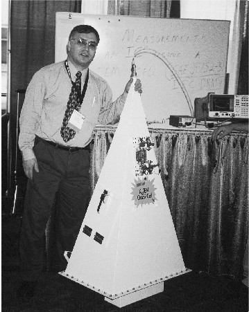
We also had a most interesting demonstration by Fred Heather of the Naval Air Warfare Center’s Aircraft Division, Patuxent River, MD which involved a lightning attachment simulator for a scaled aircraft model. I reference his paper on the subject in the 1999 Symposium Proceedings (Vol. 2, p. 640) for a detailed description of the simulation method which is quite fascinating.
Our thanks and appreciation also goes out to each of the presenters for a job extremely well done! I also wish to thank my Co-Chair Larry Cohen for his hard work and assistance in the planning and conduct of the experiments session. Last, but not least, I want to acknowledge Cliff Carroll and Jason Miller of ANDRO Consulting Services for their help in delivering, setting up, and dismantling the test equipment stations.
We have already begun planning next year’s experiments session and have a partial list of demonstrations identified. Perhaps for the 2001 symposium we will institute a formal “Call for Experiments” and set up a separate technical evaluation committee that will be responsible for selecting the experiments each year. I’ll keep you posted on the progress of this and other news concerning the future of the experiment demonstrations. If you have ideas for an experiment and want to have it considered, please contact me at (315) 334-1163 or 337-4396, andro1@aol.com to discuss your ideas. Also, periodically visit the official Washington, DC 2000 IEEE International Symposium on EMC web site to find out more about the upcoming conference and session agendas. The site will also provide a list of experiment topics being considered. We look forward to your comments and suggestions!
See you in Washington, DC!!
Andy Drozd of Andro Consulting Services may be reached at andro1@aol.com.