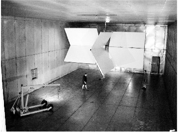
Reverberation Chambers are the latest development in EM testing, for performing radiated immunity, radiated emission and shielding effectiveness testing. Simplistically a Reverberation Chamber is much like a large microwave oven and like a microwave oven it “cooks” the test object all over. The Defence Science and Technology Organisation (DSTO) Chamber is shown in Figure 1. Reverberation Chamber development will produce a test technique that is robust (ie., highly repeatable, highly reproducible, and technically thorough). An increasing number of Reverberation Chambers are being built around the world, with general agreement on test standards and procedures. However, there is only one published standard, ED14D “Environmental Conditions and Test Procedures for Airborne Equipment” (which is Europe’s equivalent of RTCA DO 160D), with ED90 “Radio Frequency Susceptibility Test Procedures” giving more detail on the test method. In draft is IEC 61000-4-21, which will cover immunity and emission testing.
Figure 1: Inside the DSTO Chamber just after construction of the tuner.
Test houses have been using an uncontrolled version of a Reverberation Chamber for many years — i.e., a shielded room. A Reverberation Chamber is a metal box (shielded room) with a tuner. The tuner (the white object in Figure 1) is used to stir the inevitable standing waves that occur inside the room. RF energy is injected into a corner of the chamber and allowed to reflect off the walls, ceiling, floor and tuner. Inside the chamber the electromagnetic field is the vector sum of all the reflected waves arriving at any point. At each reflection the wave loses a little of its incident energy (incident magnitude) to wall ohmic losses, absorption by the test object and leakage from the chamber. The reflected waves arrive at a point inside the chamber with different magnitudes, due to the number of times the wave was reflected before arriving at the point. The reflected waves have different phase with respect to each other as a result of the different path lengths they have taken to arrive at the point. The revolving tuner changes the path lengths and the number of reflections of the waves as they arrive at a point. All this means the magnitude at any point in the chamber is different from that at any other point and different at each tuner position. However, a single revolution of an effective tuner perturbs the field to give it a known statistical distribution (i.e., chi squared with two degrees of freedom when measured with a standard linear matched antenna). The same statistical distribution is evident if many points in the field are measured, with all of the objects inside the chamber held in the same place. A typical single point measurement for a single revolution of the tuner is shown in Figure 2. Two tuner revolutions give identical tuner sweep plots. Measurements at DSTO show the shape to be identical, with magnitudes of the peaks and troughs commonly within 0.3 dB.

Figure 2: A sample tuner sweep plot.
The result of a tuner revolution is a statistically isotropic, randomly polarised, uniform field across a large proportion of the chamber volume. The useable volume of a Reverberation Chamber is approximately 50% of the volume of the chamber, significantly larger than that of an anechoic chamber. The Reverberation Chamber is a resonant cavity; hence the field inside has a resonant cavity quality factor (Q) associated with it. A plot of the Q factor for the DSTO chamber is shown in Figure 3. The field inside the chamber has a much larger (statistical) average than an equivalent open area test site (OATS) or anechoic chamber field for the same power input. Figure 4 shows the electric field for a 1 Watt input power for the DSTO chamber. An unusual feature of reverberation chambers is that the field uniformity becomes better when they are heavily loaded by a test object; however, the Q drops. Reference 1 describes these and other loading effects.
Figure 3: Theoretical and Measured Q factor for the DSTO Chamber.
Researchers in the USA have developed the theory of chamber statistical behaviour (see reference 2). The theory has provided an understanding of the nature of the field, resulting in a known statistical relationship between chamber average and maximum fields. The maximum field is 7 to 8 dB higher than the average field for a properly operating chamber. These statistical relationships have been experimentally verified at DSTO and many other places. A measurement of the average field at a number of points within the working volume of a Reverberation Chamber gives a distribution that has a standard deviation of approximately 0.5 dB, which is better than that of an anechoic chamber.
Figure 4: Average E-field achieved with 1 Watt of input power (circles for an empty chamber, crosses for a chamber with a helicopter).
Material attenuation and shielding effectiveness measurements benefit greatly from the statistically isotropic, randomly polarised, uniform field within a Reverberation Chamber. The field ensures that the least attenuation values are obtained without the need for moving antennas to get different exposure angles and polarisations. Reverberation Chamber measurements are fast, requiring only a few minutes for each amplifier/antenna combination.
Reverberation Chamber based tests will highlight any susceptibilities a test item possesses and will measure all the emissions from an object. The susceptibility found in one chamber can be reproduced in a different chamber to within mathematically derivable uncertainty. These factors are due to the isotropic, randomly polarised, uniform field within the chamber. A Reverberation Chamber test is realistic. This is because the equipment’s operational environment is often similar to the resonant cavity of the chamber (albeit with a lower Q); for example, a train, car, aeroplane or shielded room. In contrast it is impractical (although possible) to test all aspect angles and all polarisations inside an anechoic chamber due to the test time required. The field inside a shielded room is identical to that of a Reverberation Chamber except that the tuner is not present so uniformity, isotropicity and random polarisation cannot be achieved. Hence the Reverberation Chamber technique is perhaps the only technically thorough test.
This technically thorough test will provide manufacturers with confidence that their design and manufacturing processes are sound, and that their product will operate in any location (relevant to the test levels used). The consumer will benefit from products that operate without interference or causing interference.
The construction of Reverberation Chambers is relatively straightforward. A shielded enclosure is built (using conventional designs is suitable) and a tuner installed. Tuner drive systems are commercially available for modest sized chambers: the larger the tuner the better the low frequency performance. A chamber’s minimum operating frequency is defined by the chamber’s dimensions; the larger the size the lower the lowest useable frequency. The maximum useable frequency seems only to be related to the maximum power available to drive the chamber. Chamber characterisation measurements to 18 GHz have not found an upper limit in the DSTO chamber. The lowest useable frequency is related to the dimensions of the chamber and the effectiveness of the tuner. Reference 3 gives insight into the design of the DSTO chamber.
Reverberation Chamber testing is not all-good news. An understanding of Reverberation Chamber behaviour does require an open mind and some understanding of statistics. A measurement of the field in the chamber looks more like noise, as shown in Figure 2, than the deterministic field of an anechoic chamber. The isotropic and randomly polarised field inside the chamber does not give the operator any information about the direction and polarisation of the field that causes a test object to fail. A Reverberation Chamber is only able to measure the total radiated power of a test object, not the electric field at a specified distance, as required by most test standards. Some aspects of the behaviour of Reverberation Chambers are yet to be scientifically explained, despite being experimentally verified in many chambers, so research is continuing. An issue of considerable interest to Reverberation Chamber builders is the design of effective tuners which will maximise chamber useable volume.
Research is being conducted in many countries — USA, UK, Sweden, Italy and Australia to mention a few. Most EMC conferences have at least one session on Reverberation Chamber research. Much of the research is written in a highly readable form. A good place to start is the IEEE EMC Symposium proceedings of the 1990s.
In summary, a Reverberation Chamber will find all susceptibilities and allow measurement of all emissions, from all aspect angles and any polarisation. Manufacturers and consumers will benefit from the better performing products. To get these benefits, test houses will be asked to embrace this new technology.

Kevin Goldsmith is associated with the Defence Science and Technology Organisation (DSTO) at Salisbury, Australia, where his primary focus has been aircraft E3. His current research interest is the suitability of mode stirred chambers for whole aircraft electromagnetic vulnerability assessments. Kevin can be reached by e-mail at: kevin.goldsmith@dsto.defence.gov.au