

Bob Rothenberg
Associate Editor
The purpose of this section of your Newsletter is to exchange among EMC practitioners the knowledge gained from experience—both successes and failures. Articles need not be lengthy, mathematical, heavily footnoted or profound. They can reflect knowledge gained during the simulating, designing, prototyping, testing, production or deployment phases of a project, or from activities in standards development, field measurement, or materials and component testing.
The following article by Clark Vitek of CKC Laboratories proposes a common approach to test site calibration which might satisfy the many standard-setting bodies (CISPR, ANSI, IEC, ETSI) whose “similar but different” requirements for radiated emission and immunity measurements create a confusing burden for equipment manufacturers and test labs.
Reader feedback is welcome, either directly to the author or as a Letter (or e-mail) to the Editor. To submit a practical paper or article for publication, send it via fax, e-mail or snail mail to this Associate Editor. See page 3 for addresses and fax number.
Clark Vitek
EMC Staff Engineer
CKC Laboratories, Inc.
This paper describes a harmonized method to calibrate the test facility and equipment used to perform radiated electromagnetic field immunity and emissions measurements. The method is based on the use of a simulated free space environment such as a Fully Anechoic Room (FAR). A discussion of the relationship of this method with existing requirements is discussed including Field Uniformity (reference: IEC 1000-4-3)1, Normalized Site Attenuation (NSA) (reference: CISPR 22 and ANSI C63.4)2,3 and Dipole Substitution methods (reference : ETSI standards, such as ETS 300 220)4. This paper demonstrates that there is not a need for separate facilities, equipment, and calibrations and suggests that a harmonized standardization approach can be developed when a free space test facility is used for both emissions and immunity measurements. In addition, the method described in this article provides for direct calculation of measurement uncertainty in accordance with the ISO Guide for Expression of Uncertainty in Measurement5 and NIST Technical Note 1297.6
EMC standards in recent years have made it increasingly difficult for manufacturers and test laboratories to satisfy all of the required test environments and calibrations. Recent work suggested that harmonization between many of the standards is needed to reduce confusion and the burden imposed by the development of so many independent, yet clearly related standards.7 A comparison of radiated electromagnetic field test standards shows that such standards have adopted different required model environments and introduced fundamentally different definitions of the role of the test facility during measurement. Table 1 provides a comparison of three radiated electromagnetic field test standards, their required model environments, and the requirement inherent in the test standard to either compensate or not compensate for the characteristics of the test facility during measurements.
Table 1 shows that a single standard test environment and common definitions for related measurements and effects would be of benefit to the EMC measurement industry. This paper demonstrates that a method of calibration based on a simulated Free Space measurement environment can be used to satisfy the intent of all of the above standards for radiated electromagnetic field measurements, and at the same time introduce definitions of measurement uncertainty that are consistent with the ISO Guidelines for the Expression of Uncertainty in Measurement and NIST Technical Note 1297.
| Standard | Type of Standard | Required Environment | Test Facility Characteristics Bounded or Compensated during test? |
| IEC 1000-4-3 | Immunity | Free Space | Compensated (by pre-calibration) |
| CISPR 22, ANSI C63.4 | Emissions | Ground Plane | Bounded by NSA but not compensated |
| ETS 300 220, other ETSI standards | Emissions | Free Space | Compensated (by dipole substitution) |
TABLE 1: Comparison of Radiated Electromagnetic Field Test Facility Requirements for Common Standards
To illustrate the direct relationship between required NSA verification of emissions test facilities and the “Uniform Plane” calibration method of IEC 1000-4-3, one may begin with the equation for Normalized Site Attenuation (NSA) as it appears in ANSI C63.4 (1992) or CISPR 22 (1997) :
 (1)
(1)
where Vdirect is the voltage that appears on a spectrum analyzer or receiver with the feed cables connected together, Vsite is the voltage that appears when transmitting antenna to antenna, and AF1 and AF2 are the antenna factors used for the NSA measurement, which must be previously determined.
Through the relationship of power and voltage, Vdirect can be rewritten as follows assuming a matched source, line and load impedance :
 (2)
(2)
where PF is the Forward Power presented to the calibration point and RL is the Load Impedance of the receiver or spectrum analyzer, usually 50 ohms.
By definition of Antenna Factor, Vsite can be rewritten as :
 (3)
(3)
where E is the electric field presented to Antenna Number 2 (the receive antenna), and AF2 is the free space antenna factor of the receive antenna.
Substituting Equations (2) and (3) into Equation (1), the following expression is obtained :
 (4)
(4)
from which it is observed that AF2 cancels and it is immediately observed that two antennas are not required to measure NSA as long as forward power and E field can be measured. It is noted at this point that this is the method used for the IEC 1000-4-3 uniform plane calibration method which uses a single antenna for transmit, and requires measurement of electric field generated in the area to be occupied by the EUT and the forward power required to generate this field. If desired, Equation (4) can be employed directly to obtain NSA if a single, previously known antenna factor (AF1) is provided in addition to the E-Field and forward power measurement data. However, the proposed method of calibration that follows illustrates that the requirement for any previously determined antenna factors can be eliminated if the antenna, facility, and feed cables are considered together as a simulated free space measurement system and referenced to the results that would be obtained for an ideal free space environment.
As a basis for the proposed harmonization of calibration methods, the ideal far field free space characteristics of an isotropic source are taken as the baseline reference. Note that this is very similar to the ideal, short dipole pattern used for the development of NSA.8 The general relationship between electric field, E (V/m) and Power Density, PD (watts/m2) in this case is as follows:
 (5)
(5)
where Z0 is the free space impedance of approximately 120 p ohms.
The power density from a spherical, isotropic source is related to the transmit forward power, PF (watts), of the source as :
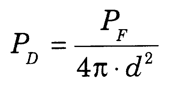 (6)
(6)
where d is the distance in meters from the source.
The power density of a source, with gain over isotropic, is then by definition of gain as follows:
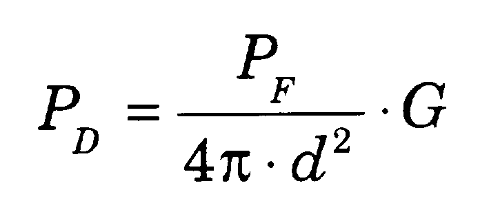 (7)
(7)
where G is the numeric power gain.
Substituting equation (7) for PD into equation (5) and converting to decibels one obtains:
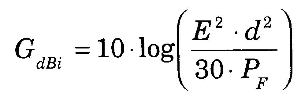 (8)
(8)
The corresponding system transducer factor, CdB, can be computed through the relationship between gain and transducer factor for an isotropic radiator as derived in SAE ARP 9589 and presented as follows (in decibel form) :
 (9)
(9)
During calibration, if the point of monitoring of the forward power is prior to the system of the feed cable to the antenna, the gain over isotropic and resulting system transducer factor include the entire system of the feed cable, antenna and non-ideal characteristics of the test facility.
This interpretation of the antenna, cables and facility as a measurement system is consistent with the IEC 1000-4-3 approach, and the Substitution methods required for measurement of emissions in the ETSI standards. In both of these standards, the calibration method results in compensation for the cables, antenna, and test facility as a unique system. However, it is important to note that this interpretation is not presently consistent with the CISPR 22 and ANSI C63.4 standards as these standards assume that the characteristics of the antenna, cable and facility can be treated as independent interchangeable components, and also that the non-ideal facility characteristics need not be compensated for during subsequent testing. This approach is viewed by this author as a non-ideal interpretation since traceability requires consideration of all known characteristics of a test system and expression of the resulting uncertainty. Furthermore, it is observed that the NSA method of ANSI C63.4 and CISPR 22 assumes that the devices of the test system act independently from each other, and can be changed out, raising the question of validity, for example, if a facility’s NSA is verified with precision dipoles for NSA and then a broadband antenna is always used for subsequent measurements. The requirement to consider the antenna, feed cables, and facility together as a measurement system allows the exact same equipment to be used for testing in the exact same geometry as was used during calibration. This is viewed as an improvement over the NSA method for the case when the same facility, antenna, and cables will always be used in the same fixed position for future testing. Furthermore, this definition of the measurement system (including the facility) allows the measurement uncertainty to be quantified based on calibration data that is specific to the facility and equipment used and inherently includes consideration of how these devices interact to simulate the ideal, isotropic free space result.
The method of simultaneous, traceable calibration of free space facilities is presented as follows:
1. With an isotropic field probe, directional coupler, and power meter, data is collected at multiple locations in the area to be occupied by the equipment under test. At each calibration frequency, the E-field is recorded as measured by the isotropic field probe and the forward power required to generate the field is also recorded. This data collection is similar to the calibration for IEC 1000-4-3. It is noted that IEC 1000-4-3 is only used as an example, and a required calibration geometry encompassing sample points over a test volume could also be utilized. After collection of the E-field and forward power data, the results are normalized to represent the required forward power to generate 1 V/m at each sample location.
2. The average power (in watts) required to generate 1 V/m is computed as follows :
 (10)
(10)
where Pfi is the normalized forward power required to generate 1 V/m at each of the individual sample points, and n is the number of sample points.
3. The standard deviation of the required normalized forward power is then also computed :
(11)
4. The system gain over isotropic is then computed from the average value of PF and equation (8) above. Note that for equation (8) a test distance must be assumed. It is suggested that by using the free space specification test distance (i.e. 3m or 10m) the resulting average gain over isotropic is computed directly referenced to the ideal, free space isotropic result regardless of the actual geometry of the sample collection points.
5. The average system transducer factor (CdB) is calculated based on PF and equation (9) above. This is the average transducer factor for the free space system to be used for future emissions measurements.
6. Note that it is recommended that Gain, Transducer Factor, and Standard Deviation be computed separately for Horizontal and Vertical polarity data populations if a linearly polarized antenna is used. Although a free space measurement system should theoretically have no difference in characteristics depending on polarity, real (non-ideal) measurement systems will show a difference at some frequencies. Furthermore, during the measurement of actual equipment under test, the transmit or receive antenna may be polarized with respect to radiation of the EUT suggesting that both polarities should be investigated.
7. The Type A (standard, k=1) uncertainty in the Gain and System Transducer Factor are calculated from the standard deviation. This value is computed as follows :
(12)
where s is the standard deviation of the sample population data, and n is the number of data points included in the computation of s. Note that for the standard 16 point IEC 1000-4-3 plane, n=16 for each polarity. The selection of equation (12) for computation of standard uncertainty instead of u=s is based on the recognition that in the ideal case for a perfect measurement system (no uncertainty), all sample locations would provide the same result. In actuality this may not be achievable, but the multiple samples collected in step 1 are intended to obtain multiple samples of the system deviation from the ideal free space result computed using the ideal free space distance in equation (8).
8. The resulting Type A uncertainty of equation (12) is then combined with Type B factors for the instrumentation used during the calibration. This includes the isotropic field probe and equipment used to monitor forward power. The Type A and Type B factors are combined by the Root Sum Squared (RSS) technique, and then expanded by an expansion factor of k=2 to represent a 95% confidence level. This represents the 95% confidence uncertainty in the Gain and Transducer values determined by the calibration.
9. For future measurements, the calibration uncertainty may be further combined with additional factors for additional instrumentation used or additional Type B considerations. An example of this is an emissions pre-amplifier, which would not be typically used for the above described calibration, but would likely be used for future emissions tests. Thus, the emissions measurement uncertainty stated for the system has to include combination and re-expansion to consider the additional uncertainty of the emissions pre-amplifier.
This article demonstrates that it is possible to develop a single, harmonized procedure for calibration of free space facilities for both radiated emissions and radiated immunity measurements. It is further demonstrated that it is possible to introduce traceability to these methods in accordance with ISO Guidelines and NIST Technical Note 1297 through the calculation of measurement uncertainty by a combination of Type A (calibration data) and Type B (instrumentation) factors. The inclusion of Type A consideration ensures that the characteristics of the individual facility and equipment under calibration are included in the expression of measurement uncertainty. The method proposed in this article would eliminate the need for separate calibration of antennas, cables, and facilities (such as in ANSI C63.4 and CISPR 22) which is likely to introduce more transfer uncertainty into the process once all parameters are considered. Furthermore, by the selection of an isotropic field probe and power meter as the principal devices to perform the calibration, no new instrumentation or calibration facilities (such as the proposed CISPR antenna calibration site)10 are needed to introduce traceability because international transfer standards already exist for the devices proposed to be used by this method. Lastly, it is suggested that the total combined, expanded measurement uncertainty, including all instrumentation, should become the primary benchmark for acceptability of facilities and measurement systems, replacing the present indirect criteria such as +/-4 dB NSA, 75% Field Uniformity, or dipole substitution. The use of total, combined, expanded measurement uncertainty as the benchmark for site and instrumentation acceptability would align the EMC community with the ISO Guidelines for Expression of Uncertainty in Measurement. The choice of Free Space as the international reference environment would permit simplified calibration methods and uncertainty calculations to satisfy the intentions of multiple present day EMC standards.
[1] IEC 1000-4-3 (1995), “Electromagnetic Compatibility (EMC), Part 4: Testing and Measurement Techniques, Section 3: Radiated, radio-frequency, electromagnetic field immunity test”, Copyright 1995 by International Electrotechnical Commission (IEC), Rue de Varembe, Geneva, Switzerland. This standard has also been published with some modifications as a European Norm entitled EN61000-4-3 (1996).
[2] CISPR 22 (1993), “Limits and Methods of Measurement of Radio Disturbance Characteristics of Information Technology Equipment, 2nd Edition”, copyright 1993 by International Electrotechnical Commission, Rue de Varembe, Geneva, Switzerland.
[3] ANSI C63.4 (1992), “American National Standard for Methods of Measurement of Radio-Noise Emissions from Low-Voltage Electrical and Electronic Equipment in the Range of 9 kHz to 40 GHz”, ISBN 1-55937-212-5, Copyright 1992 by the Institute of Electrical and Electronics Engineers.
[4] ETS 300 220, “Radio Equipment and Systems; Short Range devices technical characteristics and test methods for radio equipment to be used in the 25 MHz to 1000 MHz frequency range with power levels ranging up to 500 mW”. European Telecommunications Standards Institute (ETSI), October 1993. This reference is provided as an example of dozens of ETSI standards that accept free space measurements for intentional radiators and spurious emissions.
[5] Guide to the Expression of Uncertainty in Measurement. International Organization for Standardization (ISO), ISBN 92-67-10188-9, First Edition, 1993
[6] NIST Technical Note 1297. “Guidelines for Evaluating and Expressing the Uncertainty of NIST Measurement Results”, 1994 Edition. US Department of Commerce, National Institute of Standards and Technology.
[7] Mardiguian, Michel, “For a Better Consistency Between EMC Tests”, IEEE 1997 International Symposium on EMC, Austin Texas, pages 370 - 373.
[8] Smith, A.A, German, R.F., and Pate, J.B., “Calculation of Site Attenuation from Antenna Factors,” IEEE Transactions on Electromagnetic Compatibility, Volume EMC-24, No. 3, August 1982.
[9] SAE ARP 958. Society of Automotive Engineers, Standard 958, Revision A (Issue Date 1992-11-5). “Electromagnetic Interference Measurement Antennas, Standard Calibration Methods”, pages 4 -5.
[10] CISPR A / WG1 “Specification and Validation of a CISPR Antenna Calibration Test Site for the Frequency Range of 30 - 1000 MHz”, draft document 1997, International Electrotechnical Commission, Rue de Varembe, Geneva, Switzerland..
 Clark Vitek is EMC Staff
Engineer for CKC Laboratories, Inc. He has published multiple articles on EMC in industry
publications and at the IEEE EMC symposia. He holds a BSEE from the University of
California at Davis. Mr. Vitek may be reached via e-mail at cvitek@ckc.com.