Frank B.J. Leferink
Thales Naval Systems
Environmental Competence Centre
P.O. Box 42,
7550 GD Hengelo
The Netherlands
frank.leferink@nl.thalesgroup.com
University of Twente
Faculty of Electrotechnical Engineering
Telecommunication Engineering
P.O. Box 217, 7500 AE Enschede
The Netherlands
Leferink@cs.utwente.nl
Wim C. van Etten
University of Twente
Faculty of Electrotechnical Engineering
Telecommunication Engineering
P.O. Box 217, 7500 AE Enschede
The Netherlands
etten@cs.utwente.nl
Abstract: The impact of the geometry of a reverberation chamber, as used for electromagnetic compatibility testing, on spatial uniformity, isotropicity and quality factor are described. A new reverberation chamber with varying angles between walls, floor and ceiling and with vibrating walls is presented. Inside this Vibrating Intrinsic Reverberation Chamber (VIRC) a diffuse, statistically uniform electromagnetic field is created without the use of a mechanical, rotating, mode stirrer. Test results obtained in the VIRC are presented.
Reverberation chambers have grown in popularity for electromagnetic immunity (EMI) testing in the last decade. A reverberation chamber generally consists of a rectangular test room with metal walls and a mode stirrer, usually in the form of a large paddle, near the ceiling of the chamber. The equipment under test (EUT) is placed in the chamber and exposed to an electromagnetic field while the stirrer slowly revolves. The average response of the EUT to the field is found by integrating the response over the time period of one revolution of the stirrer. The metal walls of the chamber allow a large field to be built up inside the chamber. The EUT is therefore exposed to a high field level consisting of several different polarizations [1,2,3,4].
In classic electromagnetic immunity testing, tests are performed in a well defined, non-random environment such as a transverse electromagnetic cell or an anechoic chamber. In these deterministic environments the distribution and the polarization of the fields are invariant with time because the operational principles of these methods rely on a single dominant mode of propagation. A reverberation chamber does not give a deterministic field but provides an electromagnetic environment which is
These requirements are fulfilled if there are a large number of eigenmodes in the chamber, which is the case above a certain frequency. Furthermore the degeneracy, i.e. how many modes coincide at a certain frequency, and mode separation is an important parameter.
The main advantage of reverberation chambers is that inside such a chamber it is possible to generate high field strength using modest power sources. Therefore we need a high quality factor Q.
These aspects will be discussed in the next paragraph.
|
Figure 1. Mode separation for different chambers |
The analysis of chamber resonators requires solution of Maxwell's equations subject to the boundary conditions of the chamber walls. For simple geometrical shapes such solutions may be found by superposing incident and reflected travelling waves for the corresponding guides to produce standing waves. For nonseparable geometries ray analysis instead of modal analysis is needed. With the available calculation power this technique is not converging and thus not available. A thorough theoretical discussion about the determination of resonant modes for several chamber geometries can be found in [5, 6]. The mode separation for
chambers with equal volume is presented graphically in Figure 1. In this figure every resonance frequency (~mode) is presented as a vertical line. If adjacent resonance frequencies are within 1 MHz bandwidth then the vertical line is extended by a horizontal line. If resonance frequencies are separated uniformly in the frequency range then less vertical lines are visible. From the results in Figure 1 we can conclude that the 543-rectangular chamber gives the best mode separation
Our main objective for EMI testing is a high level of spatial uniformity and isotropicity. This can be achieved if the resonance frequencies are spread over the frequency range. Another measure for this spreading is the smoothness of the mode number function. The mode number function is the cumulative number of modes versus frequency N(f) , which is actually a discontinuous function. It can be obtained by mode counting. A smooth approximation can be calculated by observing that the wavenumber equation [7] is actually an ellipsoidal equation [6]. The volume of this ellipsoid is
 |
(1) |
where only the modes inside the ellipsoid can be used.
It can be noted that TE and TM modes of the same order have identical resonance frequencies. Such modes with different field patterns but the same resonant frequency are known as degenerate modes. This has to be considered in mode counting. Therefore the total number of modes in a rectangular chamber is approximately[6]
 |
(2) |
which is equal to Weyl's formula [4], where V = lwh is the volume of a cavity of general shape.
The more degeneracy the chamber, the less smooth is the cumulative mode number function, and the less spatial uniformity and isotropicity. The number of modes for several chambers has been obtained by mode counting. The most interesting chambers are
 |
Figure 2. Cumulative number of modes for a rectangular and cubic shaped chamber and the Weyl curve |
The cumulative number of modes for the rectangular and cubic shaped chamber are drawn with the theoretical Weyl curve in Figure 2.
Comparing the two chambers the 543-rectangular shaped chamber has lesser deviation from the smoothed Weyl curve than the cubic shaped chamber. This supports again the idea that for mode separation the dimensions of a chamber should be disassociated.
The quality factor Q of a chamber is defined as the stored energy U in the chamber divided by the power Pd that must be injected into the chamber, multiplied by the angular frequency, w = 2pf, of operation:
 |
(3) |
Four types of loss, decreasing the quality factor, have been denoted: the loss due to power dissipated in the walls, the loss due to power absorbing objects in the chamber, the leakage through apertures and the loss due to the power dissipated in the loads of receiving antennas [8]. From these loss mechanisms the wall loss is usually dominant and the only loss type applicable when comparing different chambers [7]. If we assume furthermore that a highly conducting chamber is used then the quality factor reduces to the more widely and more general expression for the first-order Q [7,9]:
 |
(4) |
where:
V volume [m3]
S surface [m2]
d skindepth [m]
mr relative permeability of wall
Our objective for EMI testing is to create a high quality factor Q resulting in a high field strength, besides the requirements for spatial uniformity and isotropicity. This can be achieved by minimising the surface S of the chamber for a given volume V. It has been shown [5] that the quality factor is maximised for a spherical chamber, compared to cubical, rectangular, circular and triangular shaped chambers. On the other hand, a spherical chamber results in the poorest spatial uniformity because the field will be focussed in the center of the chamber [5, 7].
A good compromise with respect to mode separation and quality factor could be a rectangular shaped chamber.
A reverberation chamber should yield in a high spatial uniformity and isotropicity. Chambers with fixed boundary conditions cannot fulfil these requirements, at least not below a minimum frequency.
Mode modification techniques have been investigated in the past such as:
These mode modification techniques are drawn in Figures 3, 4, 5, 6 and 7.
 |
 |
Figure 3. The Intrinsic Reverberation Chamber [10] |
Figure 4. Phase reflection gratings [11,12] |
 |
|
Figure 5. Principle of Schroedinger diffusers [13] |
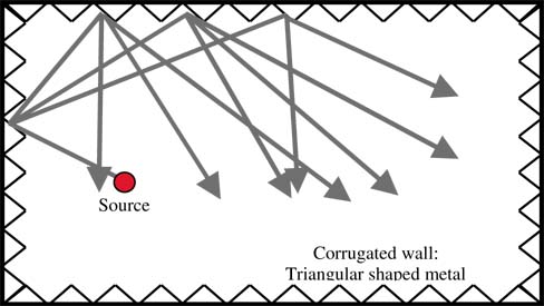
Figure 6. Corrugated walls [14] |
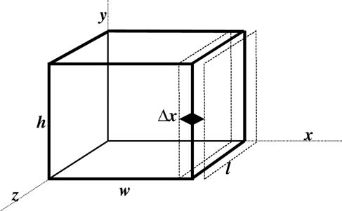 |
Figure 7. Moving wall [15] |
The IRC has never been tested in practical applications. The phase reflection gratings, Schroedinger diffusers and corrugated walls have been proven to improve the spatial uniformity of the field inside the chamber. The moving wall has been analysed but cannot be built in a practical sense.
In the next paragraph a new reverberation chamber is presented which is an optimisation of all known techniques for improved spatial uniformity and isotropicity without a decrease in quality factor.
It has been shown that the variation of the boundary conditions deviate the resonant behaviour of a reverberation chamber. For proper mode separation we need asymmetric structures. On the other hand, circular structures result in focussing of rays and thus degrade the spatial uniformity. Wall irregularities and wall-floor angle irregularities show that the spatial uniformity and isotropicity can be improved.
By changing all angles of the wall-floor-ceiling of a reverberation room at a high rate compared to the classic mode stirrer in mode stirred reverberation chambers we can use all beneficial effects. This technique is called Vibrating Intrinsic Reverberation Chamber (VIRC) and drawn schematically in Figure 8.
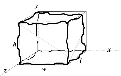 |
Figure 8. The VIRC: a flexible tent with irregularly shaped walls |
The VIRC is a reverberation chamber where the walls are made of flexible conducting material. It is mounted in a rigid structure and connected to that structure via flexible rubber strings, as shown in Figure 9. By moving one or more ridges or one or more walls the modal structure inside the chamber is changed. Because the resonance frequency shift is much larger compared to what is possible with a classic mode stirrer, the frequency range of the chamber is extended to lower frequencies compared to classic (mode stirred) reverberation chambers with equal dimensions. Note the natural corrugation of the flexible walls in Figure 9 which is beneficial for the spatial uniformity too. Another advantage is that the flexible chamber can be erected inside a standard anechoic chamber where the EUT has been installed for standard EMI tests. Because all measuring equipment is already available inside a laboratory there is no need for costly test set-up changes. Furthermore the VIRC does not need extra space inside the laboratory: it can be folded and put away fast. The most important advantage of the flexible structure of the VIRC is that it can be installed in-situ.
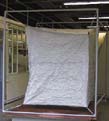 |
Figure 9. The VIRC hanging in strings |
Numerous experiments could be carried out to characterise a reverberation chamber. Some of them are:
Measurements have been carried out in a conventional MSC and the VIRC. Results of the Df, VSWR, SR, PDF, CDF and Q have been presented in [16, 17]. In this paper only some results of the frequency variation and the power density function are shown.
The field strength in the three orthogonal directions was measured inside the VIRC as function of the frequency.
An electromagnetic field was generated inside the VIRC by a log-spiral antenna (150 MHz-1 GHz). The antenna was activated by the output of the tracking generator of the Rohde&Schwarz ESS measuring receiver. The field strength inside the VIRC has been measured using the Thomson-CSF ET2003 three-dimensional E-field sensor. The output signal of the sensor was fed to the optical receiver via an optical fibre. The output voltage level of the optical receiver was measured by the ESS measuring receiver for the three axes of the field.
In Figure 10 the total electric field strength between 50 MHz and 200 MHz has been drawn for the situation that the VIRC was at three fixed positions (position 2, 3 and 4), i.e. not vibrating. The resonance frequency variation due to the changed VIRC positions is quite large, upped 10 MHz for the f011 mode, while the resonance frequency variation in the MSC is only a few MHz [17]
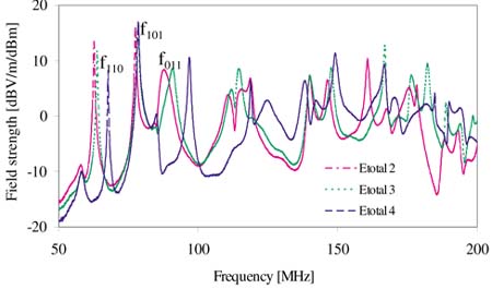 |
Figure 10. Total electric field strength as function of the frequency for VIRC position 2, 3 and 4 |
The electric field strength has been measured in the three orthogonal directions while the boundary conditions were changing; i.e. the VIRC was vibrating. The movements were random: three persons were independently moving the VIRC. The test set-up was as drawn in Figure 11. Measurements have been performed using a sample time of 1 ms for a signal frequency of 150 MHz decreasing to 0.1 ms for a signal frequency of 1 GHz.
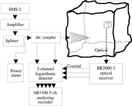 |
Figure 11. Test set-up for measuring the field strength inside the VIRC as function of change in boundary conditions |
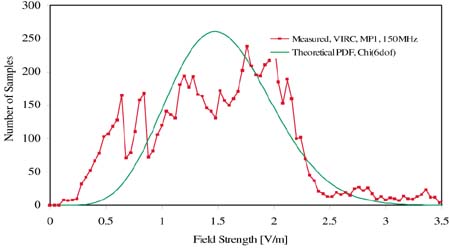
For every frequency 4000 samples have been recorded. The samples were recorded simultaneously for the incident and reflected power and the field strength for every axis, giving a total of 5 channels with 4000 samples. To obtain the probability density function the measured absolute value of the electric field strengths in the three directions were normalized. The samples of the total electric field strength have been sorted from the minimum field strength to the maximum field strength. This yields the experimental probability density function (PDF), as shown in Figures 12 through 14 for 150 MHz, 400 MHz and 1 GHz respectively.
The theory of the stochastic behaviour of reverberation chambers is described in detail in [7]. In [7, 18] it is shown that the magnitude of the electric field strength in any direction is C (Chi) distributed with two degrees of freedom, or Rayleigh distributed. This is based on the assumption that there is no direct path between the transmitting antenna and receiving sensor. If there is a direct path between the antenna and sensor then the Rayleigh distribution has to be modified resulting in the Rayleigh-Rice distribution. This distribution results in a longer tail for the total electric field strength distribution.
From the comparison between measured and theoretical PDF in figures 12, 13 and 14 we can observe that the measured PDF at 1 GHz has a longer tail than the theoretical PDF. Because the dimension of the VIRC was small with respect to the transmitting antenna, the longer tail could be caused by a direct transmission path between transmitting antenna and field strength sensor.
 |
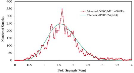 |
Figure 12. PDF for 150 MHz |
Figure 13. PDF for 400 MHz |
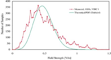 |
Figure 14. PDF for 1 GHz |
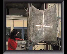
In the VIRC three fluorescent tubes are fixed in three orthogonal directions [18]. A field in the VIRC is generated by means of a generator tuned at approximately 3 GHz and an amplifier with an output level of approximately 50 W. Due to the fields inside the VIRC the lights are glowing; bright at the point with a high field strength and dimmed at places with low field strength, as shown in Figure 15. The difference in intensity can be seen in more detail in Figure 16. By moving the VIRC the field structure is changed. This results in the time-averaged constant light intensity as shown in Figure 17.
 |
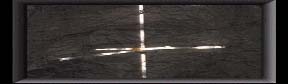 |
Figure 15. Three fluorescent tube lights in the VIRC, at 3 GHz and 50 W injected power. |
Figure 16. Detail of Figure 17. Note the difference in light intensity ~> field intensity. |
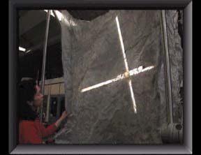 |
Figure 17. Due to the vibration of the walls the light intensity is constant over the volume of the VIRC. |
A new type of reverberation chamber to create a spatial uniform and isotropic electromagnetic field is the Vibrating Intrinsic Reverberation Chamber (VIRC). It makes an optimal use of geometry variations.
Several measurements have been performed within the VIRC and some results have been presented. It was shown that the VIRC can even change the lowest resonance frequency by more than 10 MHz.
The experimental PDF shows good resemblance with the theoretical PDF. The spatial distribution of the electromagnetic fields inside the VIRC has been demonstrated.
1. H.A. Mendes, A New Approach to Electromagnetic Field Strength Measurements in Shielded Enclosures, Wescon Technical Papers, Western Electronic Show and Convention, Aug. 20-23, 1968, Los Angeles.
2. P. Corona, G. Latmiral, E. Paolini, L. Piccioli, Use of a reverberating enclosure for measurements of radiated power in the microwave range, IEEE Transactions on Electromagnetic Compatibility, vol.EMC-18, no.2, May 1976, pp.54-59
3. M.L. Crawford, G.H. Koepke, Operational Considerations of a Reverberation Chamber for EMC immunity Measurements - Some Experimental Results, IEEE Symposium on EMC, 1984
4. M.L. Crawford, G.H. Koepke, Design, Evaluation and Use of a Reverberation Chamber for Performing Electromagnetic Susceptibility/Vulnerability Measurements, NBS Nt 1092, 1986.
5. F.B.J. Leferink, J.C. Boudenot, W. van Etten, The Vibrating Intrinsic Reverberation Chamber: an Optimal Use of Geometrical Change in Boundary Conditions, Report University of Twente, EL-TEL, Sept. 1999
6. Y. Huang, Conducting triangular chambers for EMC measurements, Meas.Sci.Technol, 10, 1999, L21-L24
7. D.A. Hill, Electromagnetic theory of reverberation chambers, NIST Technical note 1506, Dec. 1998
8. D.A. Hill, M.T. Ma, A.R. Ondrejka, B.F. Riddle, M.L. Crawford, R.T. Johnk, Aperture excitation of electrically large, lossy cavities, IEEE Transactions on Electromagnetic Compatibility. vol.36, no.3, Aug. 1994, pp.169-78
9. J.M. Dunn, Local, High-Frequency Analysis of the Fields in a Mode-Stirred Chamber, IEEE Transactions on Electromagnetic Compatibility, Feb. 1990, pp. 53-58
10. F.B.J. Leferink, High field strength in a large volume: the intrinsic reverberation chamber, IEEE Symposium on EMC, 1998, pp. 25-27
11. A.C. Marvin, J.A.S. Angus, J.F. Dawson, J. Clegg, "Enhancements to Stirred Mode Chambers by the Use of Pseudo-Random Phase reflection Gratings", Int. Symposium on EMC, Rome, Italy, 1994, pp. 218-221.
12. J. Clegg, A.C. Marvin, J.A.S. Angus, J.F. Dawson, "Optimal Phase Reflection gratings and the Effect on Fields in a Mode Stirred Chamber", Int. Symposium on EMC, Rome, Italy, 1996, pp. 86-91.
13. M. Petirsch, A. Schwab, "Optimizing Shielded Chambers Utilising Acoustic Analogies", IEEE Symposium on EMC, 1997, pp. 154-158.
14. E.A. Godfrey, Effects of corrugated walls on the field uniformity of reverberation chambers at low frequencies, IEEE Symposium on EMC, 1999, pp. 23-28
15. Y. Huang, D.J. Edwards, An investigation of electromagnetic fields inside a moving wall mode-stirred chamber, IEE Conference on EMC, Edinburgh, 1992, pp. 115-119
16. F.B.J. Leferink, W.C. van Etten, The Vibrating Intrinsic Reverberation Chamber, IEEE Transactions on EMC, 2001
17. F.B.J. Leferink, J.C. Boudenot, W.C. van Etten, Experimental Results Obtained in the Vibrating Intrinsic Reverberation Chamber, IEEE Symposium on EMC, Washington D.C. 2000
18. J.G. Kostas, B. Boverie, Statistical model for a mode stirred chamber, IEEE Transactions on Electromag-netic Compatibility, vol. 33, no. 4, Nov. 1991, pp. 366-370
19. M. Hatfield, Visualisation of Electromagnetic Fields in a Rev. Chamber, Experiments Session IEEE EMC Symposium 1998.
 |
Frank Leferink finished his studies in electrical engineering in 1984. Since then he has been an employee of Thales Naval Systems (formerly Thomson-CSF) in the Netherlands. Thales is the largest defense industry outside the US. Mr. Leferink is responsible for the EMC activities within Thales Netherlands. He initiates technology studies and is involved in EMI consultancy, research and engineering tests in the Environmental Competence Center of Thales Netherlands. This unit of 20 employees offers consultancy and performs tests for Thales and external customers in the field of mechanical, climatological and electrical environments. Mr. Leferink is president of the Dutch EMC-ESD Society, a group of 200 EMC and ESD professionals. He is also active as a professor of EMC at the University of Twente. He teaches a course on EMC and initiated and leads several related studies. His main interests are radiated electromagnetic fields generated by printed circuit boards and special test techniques. He introduced TEM cells with more than one septum, dual polarization and was also the first who applied ferrite absorbers in TEM cells. The vibrating reverberation chamber is another new technique. EMC