
|
EMC Standards Activities |
Don Heirman, Associate Editor |
| EMC standards activity can be found in various international and national
organizations. For example, in the United States the American National Standards Institute
(ANSI) accredits very active standards development organizations such as Accredited
Standards Committee C63 (EMC) which publish under the ANSI logo. Following is an article by Stephen Berger, IEEE EMC Society Standards Development Committee Chairman and ANSI ASC C63 Subcommittee 8 (Medical EMC) committee member. This article summarizes the issues related to hearing aid and cellular telephone electromagnetic compatibility which recently resulted in the finalizing of ANSI Standard C63.19 which provides for testing both the cellular phone and the hearing aid for EMC. The work was sponsored and conducted by Subcommittee 8 of ASC C63. I'd like to thank Mr. Berger for taking the time to share his efforts in the development of this new standard with our readers. Also, please note the announcement included in the shaded box within this column. The IEEE EMC Society Standards Education and Training Committee (SETCom) is once again holding its popular Workshop Session at this year's 2001 IEEE International Symposium on EMC in Montreal. It is also advertised in the Advance Program for the Montreal Symposium. Don't miss it! This is an ideal forum for those who are interested in volunteering to work on the development of new standards or revisions to existing standards. Visit informally with the seasoned professionals including the IEEE Standards Association staff that make these standards available and viable to our industry. I look forward to seeing you there. |
Early in 1996 the FCC called together a Summit between the hearing industry, the wireless industry and consumers to resolve the compatibility issue between hearing aids and cellular phones. Digital technology cellular phones were then just being introduced in the US. An interference problem with hearing aids had been discovered and a group of concerned consumer groups petitioned the FCC. The new digital telephones caused many hearing aids to "buzz" due to their RF transmission. In their petition the consumer groups asked the FCC to deal with the problem and assure that people with hearing aids would have the same ability to use these new technologies as everyone else.
As a result of the discussions held in the Hearing Aid Summit it was decided that a technical standard was needed which would identify a solution and develop tests to show that a hearing aid and cellular phone were compatible. In the spring of 1996 ANSI ASC C63 (EMC) formed task group for C63.19 to develop a measurement standard for hearing aid compatibility with wireless communications devices. The goal was to develop a set of parameters and tests that would evaluate and predict the compatibility of hearing aids with cellular phones. In January 2001 the task group completed their work and ANSI C63.19 was approved by C631. At the time of this article, C63.19 is in the last stages of being processed as an American National Standards Institute (ANSI) national standard.
The challenges presented to the task group were formidable. In order to accomplish this task several significant technical issues had to be faced. The effort required to complete this project ultimately came to include 5 research projects, and over 90 engineers from 50 different companies and organizations including the Federal Communications Commission (FCC)2 and Food and Drug Administration (FDA) working together.
The essence of the problem is that the RF energy transmitted by a cellular phone is received by the circuitry in hearing aids. Once the energy is in the hearing aid it may be audio rectified across some non-linear junction, resulting in a "buzz" of different types depending on the modulation used by the cellular phone. Significant effort has been invested in understanding and addressing this issue. This mechanism of interference is well known. The challenge in this case is that hearing aid wearers want to be able to use cellular phones. This means that the hearing aid must be located well into the near-field region of the transmitting antenna. Accordingly an evaluation of the immunity of the hearing aid must be of that immunity in the near-field environment, not the usual far field test used for immunity testing. These near fields can be an order of magnitude or larger than the "standard" immunity test field.
A second challenge faced is that, in the near-field, the fields from a wireless device are highly variable in intensity and field impedance. The quantification of the environment in which a hearing aid must operate presents a significant challenge. Movements of only a centimeter can produce significant changes in the field magnitude or impedance.
A third challenge is presented by the presence of the hearing aid wearer. The human tissue in the head and hand has a very significant influence on the field generated by the cellular phone. The question of how to properly account for this field deformation when evaluating a hearing aid's immunity presents special challenges.
A fourth challenge is that many hearing aids are equipped with a magnetic coupling mode, called the TeleCoil (t-coil) mode, in addition to the primary audio coupling mode. Testing for compatibility in this mode has its own set of challenges. For example, in this mode there is the possibility of RF interference and in addition electronic noise in the kHz region adds a second, independent, source of interference with the desired reception.
A fifth problem is that the actual annoying effects produced by the use of the cellular phone is highly dependent on the hear impairment of the user as to what is really "heard".
The measurement techniques developed for ANSI C63.19 allow the accurate evaluation of the system performance of a hearing aid used with the new generation of cellular phones or other wireless communications device. The resulting tests present new test methodology for near-field evaluation of system immunity. This addition brings a valuable evaluation tool to compliment the more mature far-field evaluation techniques, which are available.
Workshop Session on the Development of IEEE StandardsA repeat of the popular Workshop Session on the development and adoption of standards given at the 2000 IEEE International Symposium on EMC in Washington, DC will be held this year on Monday, August 13, during the 2001 IEEE International Symposium on EMC in Montreal. Topics to be addressed include IEEE requirements on standards development; computer-based tools now available to support working groups and others working on the development of new standards or on the revision of existing standards; suggestions for managing working group meetings and activities; and personal perspectives of current and recent working group chairs. All persons who are currently members of IEEE EMC standards working groups or anyone who is interested in learning more about standards development activities, whether IEEE or others, are invited to attend. Check the Advance Program for the 2001 IEEE International Symposium on EMC in Montreal for the location of this Workshop Session. Be sure to register for this informative Workshop Session when you send in your Advance Registration. Questions? Comments? Please contact Hugh Denny, EMCS Standards Education and Training Committee (SETCom) Chairman, at phone 404-633-9363, e-mail: hugh.denny@gtri.gatech.edu |
The objective of the wireless hearing aid compatibility effort is to provide for good system performance between hearing aids and wireless devices. This section discusses the logic by which this objective is parameterized and target values are assigned to those constituent parameters.
The first step is to normalize the test for normal speech. 65 dB SPL (sound pressure level referenced to 20 mPascals) is a nominal value often assigned to normal speech. For the purposes of this discussion, the complexities of frequency differences within the audio frequency band will be disregarded. So, for any given frequency in the audio frequency band a level of 65 dB SPL is assumed to deliver normal speech. A hearing aid increases this nominal level by some gain factor in order to compensate for the user's hearing loss. Other processing may be involved, such as noise cancellation or automatic gain control. However, at any given point in time a hearing aid may be assumed to receive an input signal, nominally at 65 dB SPL, and deliver to the user a signal of (65 + G) dB SPL, where G is the gain at the frequency of interest.3
In order to normalize the hearing aid parameters the standard related all parameters to an equivalent input. So the interference measured at the hearing aid output has the gain of the hearing aid subtracted from it. The result is the sound level, which if presented to the input of the hearing aid would produce the measured output. In this way the variances of gain between hearing aids is normalized out of the measurement.
In order to be intelligible the signal delivered to the user must have an acceptable signal to noise or signal to interference ratio. Three performance categories have come to be commonly used, which may be characterized as: usable in an emergency, acceptable for normal use, and excellent performance. Various research studies4 have indicated that a speech to interference ratio of 20-26 dB is acceptable for normal use. A 10 dB degradation, to a range of 10-16 dB, yields a system which could be characterized as usable in an emergency but inadequate for regular use. Alternatively, an improvement of 10 dB, to a range of 30-36 dB, yields an excellent performance level, where there is little discernible noise or interference. Taking 20 dB signal to interference as a nominal target performance criterion results in a 45 dB SPL, input related, level for interference. Equivalent target parameters may be derived for the other performance categories.
The target performance is then parameterized and allocated between the system components, the phone and hearing aid. The picture is further complicated by the fact that this equipment operates within the near-field region of the phone's antenna and body. Yet further complication is created by the field perturbation from the user's head and hand and other nearby objects. Setting these complications aside for the moment, a general division must be made between the E and H field performance of the hearing aid. So target immunity for both the E and H field must be set for the hearing aid. These immunity targets must be coordinated for both near-field E and H field of the radiating device, in the area controlled for the use of the hearing aid. Hence, when phones provide fields at or below the emission limits and hearing aids exhibit immunities at or above the immunity targets the required audio performance will be delivered.
Next, the t-coil coupling mode must be dealt with. In this mode a hearing aid receives its signal not by a microphone but through an inductive pickup coil. The intended magnetic signal for the t-coil is that produced by the audio signal driving the phone receiver element or some other inductive circuit element. In the ideal case a hearing aid delivers the same audio level whether in audio or t-coil mode. Going back to the 65 dB SPL level for normal speech, some magnetic field emission level may be assigned to it. The hearing aid in t-coil mode receives this signal inductively and amplifies it to the same (65 +G) dB SPL level which it would deliver if the user were using the microphone mode. The intended advantage of this system is that any audio background noise is not received and so the user receives a better signal.
However, in the case of a cellular phone there is a lot of electronics in the handset, unlike landline corded-phone handsets. The electronics also emits magnetic fields from the currents in the circuitry. These emissions are received as noise to the intended audio signal. In order to deliver the desired performance two criterion must be met. First the user of a hearing aid in t-coil mode should receive a signal of (65+G) dB SPL for a normal speech level emission. Second that signal should have a noise component of no more than (45+G) dB SPL. In paramaterizing this, the phone must deliver a magnetic field of the intended audio signal within a defined target window. The hearing aid is then responsible for receiving this signal and amplifying it to the intended (65+G) dB SPL level.
Orientation effects further complicate this picture. If the hearing aid's inductive coil is cross polarized to the field then a significant loss of reception will result. This must be left for the user to adjust for optimum reception.
In the t-coil mode there are two distinct noise sources. The currents in the phone's circuits will create magnetic emissions in the audio frequency band used by the intended signal. Secondly, the RF fields may be audio rectified within the t-coil circuits exactly as they are for the microphone mode. The combined effect of these independent interference sources must be below the (45+G) dB SPL level.
In order to achieve the desired target performance for t-coil mode a number of parameters must be met by the hearing aid involved. For the cellular phone a magnetic emission must be delivered which is within some defined relationship to its acoustic output. Further, this signal must have an intended signal to interference ratio of 21 dB or better. The change from a 20 to a 21 dB target allows for the addition of RF interference noise. Other partitions, which sum to the same 20 dB, final performance figure are possible. The phone must also provide RF E and H fields below set levels in the area intended for use by the hearing aid.
The hearing aid must then receive and amplify the magnetic field, provided by the phone, to the same level it would the matching acoustic signal. It must not add any significant noise to the signal from its own circuitry. In addition, it must provide an immunity to the RF E and H fields such that the signal received at 21 dB signal to interference is delivered at the desired 20 dB quality level.
In summary then, in order for a hearing aid and cellular phone to operate as desired the requirements listed in Table 1 must be met.
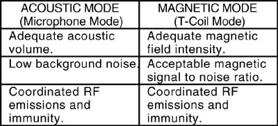 |
Table 1. Operational Requirements |
From these requirements the following parameters must be observed for wireless phones and hearing aids to deliver the desired system performance:
In the Acoustic Mode:
In the T-Coil Mode:
These parameters result in the need for five measurements in order to assure that the intended performance will be achieved. These measurements are:
ANSI C63.19 controls an area 5 cm square for use by a hearing aid (See Figure 1). This area is defined as being 1 cm from the surface of the phone, over the area of the receiver. Specifically it begins at the top edge of the body of the phone and comes down over the receiver area of the phone. It is centered, left to right, about the centerline of the phone. The field strength in this area is to be scanned using near-field probes for both the E and H field. Because the area is deep within the near-field of the antenna, sharp field gradients are common. Field variations of over 100 V/m can be found within this 5 cm square area. Hence, it is vital that careful scans of the entire area be made to accurately assess the peak field potential.
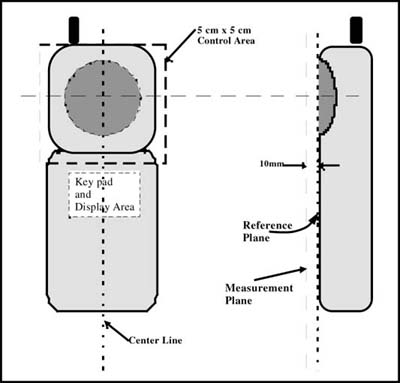 |
Figure 1. Control Area for Hearing Aid Use |
The concern in assessing these fields is the interference potential of the emissions. Therefore, it is the peak field value which is of interest with the cellular phones operating at their maximum power. Probes and their supporting instrumentation system must be capable of fast response. For example, in TDMA (Time Domain Multiple Access) cellular phone protocols a unit transmits in a specified time slot. It is common for the transmitter to function only one eighth of the time. So for a 600 milliwatt system the average power transmitted will be 75 milliwatts. For this reason probes which use diode detection are preferred. Even with these systems it is common to perform averages either in the A/D conversion process or at other locations in the instrumentation software. For the purpose of assessing the interference potential the peak reading is the required value.
In considering the immunity of a hearing aid to RF emissions the near-field immunity is of interest. The standard measures the immunity using a resonant half-wave dipole tuned to the center of the cellular phone bands.
The near-field test is performed by feeding a resonant dipole, tuned to the prescribed frequency with a specified amount of power. The hearing aid being evaluated is tested near the center and tip of the dipole. The fields produced by the dipole are predominately H field near the junction of the dipole and predominately E field near the tip of either element. So by exposing a hearing aid to the field near the dipole junction and to the area near the tip both an H and E field immunity test is performed. In order to achieve good repeatability great care must be taken to control the spatial parameters involved. The region, which contains the peak emission within 10%, is less than 1 cm in any direction. In the direction tangential to the dipole the peak field falls off by more than 10% with a very few millimeters. Because of this sensitivity to location, a mechanical fixture allowing small movements is required during the tests.
Standard measurement techniques for the audio frequency magnetic emission of landline corded phones have existed for some time. FCC Part 68 sets for the required limits for these signals and EIA RS-504 and IEEE 1027 set forth the specific measurement procedures. However, these procedures, while helpful, are not sufficient for the situation with wireless telephones. The levels established for landline corded telephones are not appropriate for the technologies being used for wireless devices. Three major factors must be considered in addition to the factors involved in testing landline corded phones for FCC Part 68 hearing aid compatibility compliance. First, the RF transmission of the phone may affect the test equipment being used and create inaccuracies in the testing. This is often circumvented by redirecting the RF to an auxiliary antenna port on the telephone under test. However, even in this case the residual RF leakage can produce fields of 30 V/m or more in the region very close to the phone. The test procedure used must assure that any RF, including any residual RF, does not affect the test.
The second major issue is the question of signal quality. With landline corded phones it is assumed that there is not a significant possibility of noise emissions adding to the intended audio magnetic emission. So if a magnetic field of the required amplitude is measured it is assumed that this signal is produced by, and carries, the acoustic signal being delivered by the telephone receiver. This is not the case with cellular phones. Battery current surges, keyboard scanning and display currents can produce significant emissions of their own which will add noise to a t-coil mode hearing aid. It is important to measure first the emission level without signal, which is the noise level from these other sources. Then the signal is introduced at its intended level and the measurement is remade. The second measurement is a signal plus noise measurement. Thus a signal plus noise to noise assessment of signal quality may be made. The division being made is that the telephone must deliver an audio frequency magnetic emission with an acceptable signal plus noise to noise figure. The hearing aid must then deliver this signal to the user without adding significant additional noise to it, either from its own circuitry or, more probably, by audio rectification of RF emissions.
The third consideration is the assurance that the telephone's mode of operation during the test is truly representative of its normal operating mode. The advanced signal processing algorithms used in cellular telephones often will treat a test signal in a very different manner than an actual voice signal. This will be discussed more fully in a separate section below. However, the simple test signals which are fully adequate for landline corded phones are not effective in cellular telephones. For example, currently it is most common to induce a test signal at a specified voltage onto the tip and ring (signal) lines to a landline corded telephone being tested. The signal path from that point is sufficiently standard that the acoustic signal emitted from the phone is reasonably determined. So for the magnetic field test the test signal is put onto the telephone lines and the magnetic field at the phone handset receiver is measured. An alternative, which does not assume this fixed relationship between input and acoustic output, calls for the receiver output to be established at a specified volume. Then the magnetic field is measured. Thus the relationship being sought is a fixed relationship between the acoustic output and the magnetic field output. Care must still be taken to assure that the test signal being used has the cellular phone's various gain and other settings at similar levels to those created by an actual voice signal.
The ever-increasing use of electronics creates defacto systems that must operate acceptably. However, these systems may not be under the control of a single company or even a single industry. The case discussed here of cellular telephones and hearing aids is a case in point. There is a societal desire and a commitment from both the cellular telephone and hearing aid industries that these devices operate well together. ANSI C63.19 was developed by both industries to provide the requirements and validating tests required to make that commitment a realized reality in the marketplace.
1. EIA RS-504-1983, "Magnetic Field Intensity Criteria for Telephone Compatibility with Hearing Aids.
2. EHIMA GSM Project, Development phase, Project Report (1st part) Revision A, Technical-Audiological Laboratory and Telecom Denmark, October 1993.
3. EHIMA GSM Project, Development phase, Part II Project Report, Technical-Audiological Laboratory and Telecom Denmark, June 1994.
4. EHIMA GSM Project Final Report, Hearing Aids and GSM Mobile Telephones: Interference Problems, Methods of Measurement and Levels of Immunity, Technical-Audiological Laboratory and Telecom Denmark, 1995.
5. FCC 47 CFR 68, Connection of Terminal Equipment to the Telephone Network (1997).
6. Hearing Aids/GSM, Report from OTWIDAN, Technical-Audiological Laboratory and Telecom Denmark, April 1993.
7. Joyner, K.H. et al, Interference to Hearing Aids by the New Digital Mobile Telephone System, Global System for Mobile (GSM) Communication Standard, National Acoustic Laboratory, Sydney 1993.
8. Joyner, K.H. et al, NAL Report #131, National Acoustic Laboratory, Sydney.
9. IEC 118-4: 1981, Methods of Measurement of Electroacoustical Characteristics of Hearing Aids - Part 4: Magnetic Field Strength in Audio-Frequency Induction Loops for Hearing Aid Purposes.
10 IEC 118-13:199x (Draft), Methods of Measurement of Electroacoustical Characteristics of Hearing Aids - Part 13: IEC 77B/153/CD June 1995.
11. IEEE Std 1027-1996, IEEE Standard Method for Measurement of the Magnetic Field in the Vicinity of a Telephone Receiver.
12. McCandless, G.A. & Lyregaard, P.E., Prescription of Gain/Output (POGO) for Hearing Aids, Hearing Instruments 1:16-21, 1983.
13. Technical Report, GSM 05.90, GSM EMC Considerations, European Telecommunications Standards Institute, January 1993.
 |
Stephen Berger is president of TEM Consulting, an engineering services and consulting firm, located in Austin, Texas. He was co-chair of the ANSI C63.19 committee with Tom Victorian of Starke Labs. Mr. Berger has worked in EMC (Electromagnetic Compatibility), RF Safety and Disability related issues for 20 years. He has served on two federal advisory committees, the Telecommunications Access Advisory Committee, in 1996, and the Electronic and Information Technology Advisory Committee, in 1999. Currently he is:
He has written numerous technical papers and holds several patents in the area of EMC and Access technology. He may be reached at stephen.berger@ieee.org. EMC
1 The same problem was being addressed in Australia and later in Europe. See references 2-4, 6-8 and 13.
2 A standard for Hearing Aid Compatibility (HAC) in corded phones had been developed by EIA and incorporated into the FCC rules for Part 68. However, this solution is not effective for cellular phones for several reasons, the most prominent is that it does not address the interference problem. See references 1, 5 and 11.
3 This work assumes hearing aid performance is consistent with the standards for that industry. See references 9-10 and 12.
4 The three primary North American Studies have been performed by Dr. Schlegel and the University of Oklahoma Center for the Study of Wireless EMC, Dr. Levitt of CUNY with Dr. Harkin of Gaulludet University and Dr. Killion of Etomotic Research. The research focus and protocol of each study was different. However, the conclusions of these studies have shown remarkable consistency on the fundamental issues involved.