
In the past, extensive study has been made on the theoretical modeling and experimental validation of the parameters influencing the response of a transmission line (TL) illuminated by external electromagnetic waves or lumped voltage sources along the length of its conductors. Summarizing these parameters, one can mainly state: the per-unit-length losses of TL, the length of TL compared to the wavelength of the excitation waveform, the behavior of non-linear termination loads, the presence of lossy earth, etc. According to the specific configuration of the problem, numerical as well as analytical models have been introduced in the literature, both in time and frequency domain. One of the most commonly used models is the Finite Difference Time Domain (FDTD) technique. This technique has become popular due to its versatility and the ability to incorporate several modifications related to the configuration of the problem. In this paper, we highlight the alterations observed on the far-end induced voltage of the TL, associated with the non-uniformity of the TL.
It is of great importance to note that the study of the behavior of the induced voltage of TLs in the time domain is very interesting, especially in modern broadband communication systems using Direct Sequence Code Division Multiple Access (DS-CDMA). When the transmitters in such a system operate close to each other, the emissions from one transmitter influences the TL circuit driving the front end of the other, and this fact gives rise to intersymbol interference. As the orthogonality of the pseudo-random sequences in DS-CDMA is prerequisite, the induced voltage will probably alter this substantial property. On the other hand, the operation of TLs in the presence of an external E/M wave may probably result in data asymmetry. The use of an FDTD model for simulation purposes in such cases offers a great advantage in the EMC design of modern wireless communication systems. A comprehensive analysis of such phenomena will be presented in a future paper.
Under the assumption of TEM mode propagation along the line, its behavior can be described in terms of circuit-theory parameters. Consider a TL of z-directed, total length L and x-directed distance of separation between the conductors equal to d, terminated in resistive loads Rs , RL. The mathematical representation of TL excited by an external electromagnetic wave with angle of incidence q, consists of a system of two coupled integro-differential equations written as:
(1a)
|
(1b)
 |
where V(z,t),I(z,t) is the line voltage and current, respectively, l, c is the per-unit-length inductance and capacitance of the lossless TL (r=g=0), and finally, ET, EL are the components of the incident electric field vector.
The FDTD technique seeks to approximate the derivatives in equation (1) with regard to the discrete solution points defined by spatial and temporal cells. For this purpose, the length of TL is divided into K sections of length Dz, and the total time of coupling phenomenon observation is divided into N sections of Dt. According to this notation, the line voltage and current can be formulated as written below:
(2a)
(2b)
Additionally, the forcing functions can be expressed in a similar form.
As it can be readily seen from equations (2), we interlace the voltage and current points in order to insure second-order accuracy of the discretization. Finally, the terminal conditions are implemented into FDTD code by:
(3a)
 |
(3b)
 |
By applying the concept of FDTD technique into equations (1), the final form can be written as:
(4a)
 |
(4b)
 |
(4c)
 |
(4d)
 |
The above equations can be solved in a "bootstrapping" fashion. At each time step n, the voltages along the line are computed in terms of the previous voltage and current values. Afterwards, the currents along the line are evaluated for the next temporal cell. This procedure ends when time reaches the total time of observation. In order to insure stability of this leapfrog scheme, the following condition must be fulfilled:
(5)
 |
known as the Courant condition, where u is the speed of light.
In the majority of previously published studies, the per-unit-length inductance and capacitance is considered of constant value; that is the case of uniform TL. In our study, the height of the upper conductor, d, is a function of z. In order to show the discrepancies observed in the induced voltage, due to non-uniformity of the TL, we will compare five TL configurations of similar geometrical and excitation characteristics. In Table 1, the common characteristics of all TLs under study are presented.
 |  | |
Moreover, in Table 2, the function of d=d(z) for each TL is listed.
In Figure 1, the induced voltage at the far-end is depicted for the line configurations. Although the lines under study are quite similar to each other, the variations between their voltages are large. This is due to two main reasons: The first one is related to the strong dependency of the voltage response to the inductance and capacitance. In other words, each spatial cell Dz results in different values of l, c. On the other hand, the external E/M wave travels more or less time (depending on the configuration of the line) to impinge the non-uniform line. Thus, the time interval needed for the wave to impinge the line between two successive spatial cells is not constant, as in the case of a uniform TL.
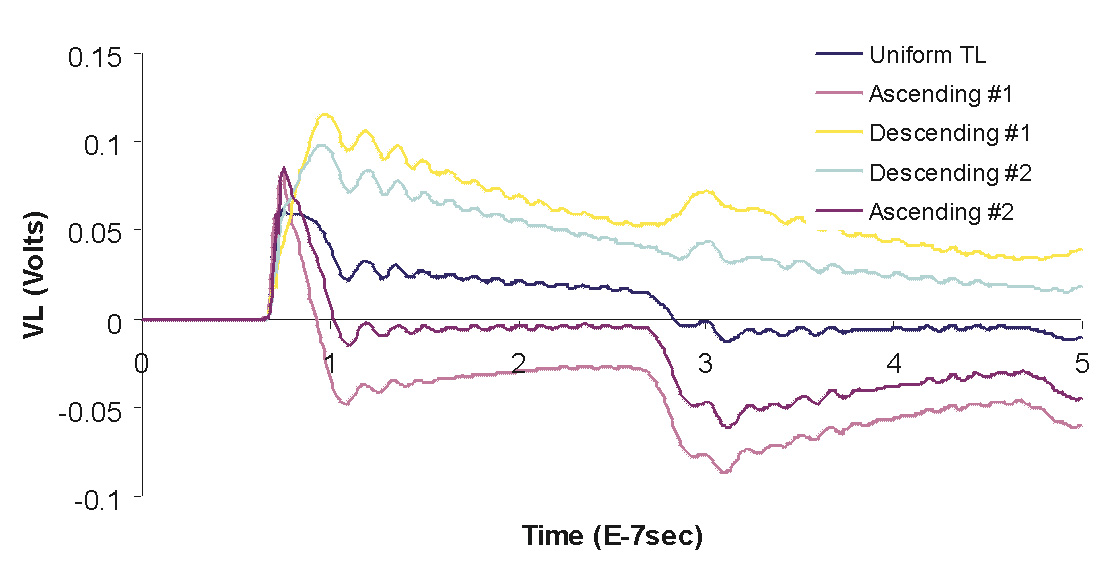 |
Figure 1. Transient Response of five similar TL configurations |
Due to the versatile nature of FDTD code, the excitation waveform can be chosen to be sequential rectangular pulses on a carrier frequency and thus describe the interference caused in digital communication systems.
The important conclusion arising from this work is that an additional parameter must be taken into account when dealing with the coupling phenomenon present when a TL is illuminated by an external electromagnetic wave; that is the non-uniformity of the line configuration. It was shown that slight inclinations of the conductors could result in great alterations in the voltage response of the line. From a designer's point of view, this property can be used as a useful tool in the design of immune TL configurations by choosing the proper inclination, termination loads and other geometrical characteristics of the line.
 |
Panagiotis Trakadas received his Diploma of Electrical and Computer Engineering and the M.E. Degree from National Technical University of Athens, in 1997. He is currently working towards his Ph.D. thesis at NTUA. His research interests include time-domain techniques and computational modeling of MTL problems and OATS performance. He is a student member of the IEEE EMC and AP Societies.
 |
Christos Capsalis is currently a Professor at the National Technical University of Athens and Director of its Wireless Communications Laboratory. He has organized post-graduate courses in EMC at NTUA and at local companies. His current research activities include wireless and satellite communication systems and EMC.