 |
Table 1. 30 MHz Dipole Properties * |
Colin E. Brench
Compaq Computer Corporation
200 Forest Street
Marlborough, MA 01752
colin.brench@compaq.com
Bronwyn L. Brench
EMC Consultant
73 Crescent Street
Stow, MA 01775
bonnie.brench@usa.net
Most EMC engineers are very familiar with working in a test lab, and devising experiments to help isolate the source of an emissions problem and a means of controlling it. However, give many of these same engineers access to sophisticated electromagnetic simulation software, and there would be a moment's silence before confusion sets in. Exactly the reverse applies to those tasked with the development of electromagnetics simulation tools. Offer them the opportunity to use a state-of-the-art measurement facility, and the same silence and confusion results. To be fair, there are more and more EMC engineers with a foot in both the hands-on measurement world and that of computational electromagnetics. It is the intent of this paper to help more engineers understand both sides of these still separate arts, particularly as the problems encountered developing a good EMI experiment are in fact very similar to those faced when creating EMI models.
EMI measurements are made on a product after completion to evaluate whether or not that product's EM emissions are within specified limits. Measurements are also very beneficial during the development of a product, on component subsets of that product, to evaluate the behavior of a particular assembly. There are a number of reasons for the EMC engineer to develop special experiments but, at the root of them all, is the need to understand the physics behind a particular behavior. Such investigations are often done to evaluate the coupling paths between an RF energy source and a radiating element, for example, to gain an insight to the radiator itself or to determine specific parameters such as the magnitude and impedance of a particular source or the radiated field strength due to a particular configuration. Such detailed measurements are necessary to gain a full understanding of the product, and to quickly and efficiently bring that product to market.
EMI modeling is done for the same reason as the laboratory measurements, but with one additional critical driving factor Ð the absence of any real hardware. During the early stages of product development with nothing physically available to measure, the use of computer modeling is the only practical choice to evaluate an unknown structure.
Computer modeling of EMI problems requires creating a model that represents the key physical and electrical properties of the device of concern. The model must be prepared in a suitable way to provide input to the simulation software tool. In the context of this article, modeling refers to the complete process of model creation and the running of the simulation software.
Modeling can give an engineer a head start on the development of a computer system. With the concurrent design practices in industry today, it is often necessary to perform system level design work in parallel with the development of the components for that system. For example, a high performance computer system enclosure is designed, built, and waiting for the completion of the processor and other similar devices. Until all the pieces come together, the complete system cannot be measured; however, there are many details known for both the system and the processor from the early stages. Developing computer models of the processor and the system at this early stage can be essential in finalizing the EMC design quickly and in a cost effective manner. Modeling is an excellent way to gain an understanding of the electromagnetic behavior of individual parts of the system.
Given the fact that modeling and measurements are often being performed for the same reasons, it should not come as a surprise that the difficulties associated with both are also very similar. To put these issues into proper perspective, a variety of measurement concerns are examined, together with the equivalent modeling concerns. These concerns include:
When making field strength measurements on an open field test site, there are some basic requirements that must be met such that the desired accuracy is obtained. One of these requirements is that there is a reflection free zone surrounding the device under test (DUT) and the test antenna. The minimum size of this zone is well defined in the measurement standards, and sized to ensure that any reflections from small objects at the edge of the zone will not cause significant errors in the measured field strength. However, if large or multiple objects are outside the defined reflection free zone, they can still influence field strength measurements. To this end, most test houses make the free zone significantly larger than called for by the standards. In reality, this practice works for most measurements, and the enlarged reflection free zone is given little further consideration other than to ensure that it is indeed kept clear. However, there always remains the risk that objects at the edge of the zone will impact measurements, thus causing errors.
The parallel to the reflection free zone in modeling is the use of absorbing boundary conditions (ABCs) that are required for volume-based modeling techniques, such as the Finite-Difference Time-Domain (FDTD) and Finite Elements Methods (FEM). In such techniques, the entire space of the problem is broken into small elements, and the fields for each element are computed. While free space is infinite, practical computer modeling requires the use of a finite computational domain, preferably as small as possible to minimize the size of the problem to be solved. ABCs of some kind are necessary to truncate the computational domain. As the ABCs are imperfect they have to be kept at a suitable distance from the other model elements and, so here again, if the domain is made too small, reflections errors can creep in.
ABCs are the mathematical equivalent of the absorbing materials used in a shielded room to make it into an anechoic chamber. Boundary conditions of this type are carefully crafted to minimize reflections from the edges of the computational domain. There are some foolproof ways of using ABCs; unfortunately, these all require significant amounts of additional volume to be included in the model. To create an efficient model, this additional volume must be minimized, so the use of the ABC that is part of a particular problem needs to be understood. Understanding is required of both the conditions that apply to the specific ABC, and the requirements for placing it sufficiently far from the model.
Some numerical techniques, such as the Boundary Element Method, better known in EMC circles as the Method of Moments (MoM), are surface-based rather than volume-based. These techniques typically solve for the currents on the surfaces of all conductors, do not utilize a computational domain, and thus free the user to construct a model without the need of an ABC. Inherent in the formulation of these surface-based techniques are the means to simulate the free space environment (within the Green's functions). In this case, the author of the code has the responsibility for setting the behavior of the simulation, rather than the code user.
Whenever a measurement is made, there is an understanding that the presence of the probe will in some way affect the measurement. A voltage probe will require the addition of a shunt impedance, and a field strength measurement made close to the DUT will have an effect on the calibration of the measurement antenna. Indeed, measurement antennas themselves can be considered as large field probes, and they are not immune from loading effects. Antennas will couple to all conductors nearby, including the test site ground plane, feed cable, and possibly also the DUT. The magnitude of these loading effects is understood and expected.
When modeling the DUT, the measurement probes have no physical existence, so there are
no loading effects. This is an advantage when the goal of the model is to determine a
field distribution, terminal impedance, or any other parameter that is adversely affected
by loading. However, this can be a problem if there is a need to correlate the modeled
results with those of a measurement. In this case, either the effective loading impedance
or a model of the physical probe being used must be included.
The use of modeling to support EMC measurement methods is just beginning to have an
impact. The measure of acceptability for an open field test site is site attenuation. In
the early days of FCC testing, the reference to which all sites had to be compared was
partly theoretical and partly empirical. The reason for this was understood, and is
related to the direct coupling between antennas, particularly at the low frequencies of
concern. However, as these effects could not be suitably calculated, the empirical model
was needed. As test methods have developed, the inaccuracies in this early reference
became more important, and good test sites would not always meet the requirements. Highly
refined models for site attenuation are now possible through the use of computer modeling,
and can account for the different results for a variety of antenna types.
Other practical applications of modeling of measurement configurations are becoming an important adjunct to measurement technology. As the position of an antenna is changed with respect to the test site ground plane, both in height and in polarization, its properties are subtly affected. A low horizontal antenna is very tightly coupled to the ground plane, and so its self-impedance changes. For the vertical case, the balance of the antenna is also upset. These changes add to the uncertainty of any measurements made by the antenna. The simple example of a 30 MHz tuned dipole located at different positions is modeled, and the results are shown in Table 1. Three cases are computed for the dipole: in free space, horizontally polarized at a height of 4 m above the ground plane, and vertically polarized with the lower tip of the dipole 25 cm above the ground plane. These latter two positions are those most likely to be used during real EMC measurements near 30 MHz. It is assumed for this example that the antenna is perfectly matched for the free space condition. The mismatch loss represents an uncertainty in the final field strength measurements.
 |
Table 1. 30 MHz Dipole Properties * |
A similar effect can be observed when the antenna feed cable is parallel to the antenna polarization. If the cable is free to hang in different locations each time the antenna height is changed, yet another uncertainty is added to the measurement, as the cable coupling effects are free to vary differently each time. Table 2 shows the change in mismatch loss for a vertically polarized, 30 MHz tuned dipole. The dipole's lower tip is positioned 25 cm above the ground plane, and the feed cable position is moved in steps from 1.0 to 2.0 m away from the antenna element. It can be seen that an additional uncertainty is added into the measurement of field strength.
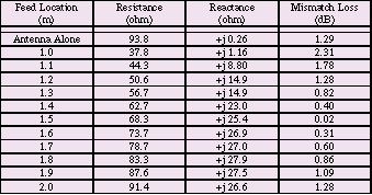 |
Table 2. 30 MHz Dipole Properties with Feed Cable * |
A diagram of the model used to compute the data in Table 2 is shown in Figure 1. It can be seen that the model is very simple, containing only three wire conductors, yet it provides data that supports improvements in practical EMI measurements. Many test laboratories include ferrite cores on antenna feed cables to break up the induced currents. The addition of these ferrite cores results in the minimizing of the variable mismatch losses. The data in Table 2 supports this practice and shows the improvements that can be expected. It should be noted that for a poorly matched antenna, the effects can be greater than for this simple example case.
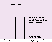 |
Figure 1. Wire Model of 30MHz Dipole with Feed Cable |
Through experience, it has been found that regular symmetrical shapes are not ideal for a variety of RF test facilities, including compact antenna ranges and EMI open field test sites. Compact antenna ranges are designed to simulate free space in a very short distance through the use of large reflector antennas. These reflectors are designed with angled edges to minimize large in-phase reflections. Rather than maintaining symmetry, EMC test sites are built with the antenna and turn table locations off axis with respect to the ground plane and any weather protection structure.
Exactly the same problems can arise when creating a model, and the same precautions are necessary; namely, ensuring that the main components are offset. These symmetry problems are due to the perfection associated with CAD tools. An ideal, physical box has perfectly orthogonal walls, but reality dictates that there are small imperfections in the construction. Many small details exist in a real box; these include draw angles, bowing, offsets for joining seams, and internal mounting brackets. These all limit the geometric perfection, and real material properties also add RF loss into the physical model. By comparison, a modeled box is often specified to be absolutely perfect in its geometry and to have a loss free nature. Typically, all the small details listed do not play a significant role in the EMC performance of the real box. Since they are not needed, they are not specifically included in the model; however, unless specified, a CAD tool will create a box that is perfect.
There are additional problems when modeling, similar to that of the perfect box. These problems are also due to the perfection possible with CAD tools. A good example of this CAD tool characteristic is the well-known attribute of any graphics interface Ð the ability to snap objects to a grid. This ensures that all elements in a model are perfectly aligned with respect to the x-, y-, and z- coordinates. As a result, all source elements will be perfectly aligned with other elements of the model. Similarly, when a source is specified, it will have pure polarization; while in reality, a noise source is rarely aligned exactly to the model coordinates, nor is it pure. Either of these examples can completely eliminate any cross-polarized fields from existing in the model. This might not be a problem, but it is not unknown for a cross-polarized response to dominate in the overall EMI performance of a system. If these effects are critical, their lack can result in very misleading conclusions.
Perfect model geometries can also be a serious problem for simulation tools that function in the time-domain. Such codes effectively work by obtaining the impulse response of the structure being modeled, applying a stimulus, and letting the structure ring down to its quiescent state. With perfect geometries and parallel walls, it is quite possible for energy to become trapped, preventing the impulse response from dropping down to zero. To address this, some loss must be introduced.
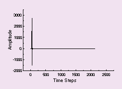
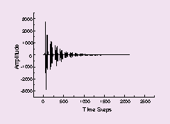
Time-domain examples showing the impulse response in free space between two perfectly parallel walls and between two non-parallel walls are shown in Figures 2, 3, and 4 respectively. It can be seen how rapidly the non-parallel case settles compared to the case with parallel walls. It should be noted that this is not an enclosed space, just two parallel walls. The decrease in ringing time in Figures 3 and 4 is due to energy being reflected to the absorbing boundaries rather being trapped between them. These examples were prepared using a two-dimensional FDTD code.
 |
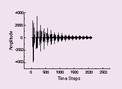 |
Figure 2. Impulse in Open Space |
Figure 3. Impulse Response Between Two Parallel Walls |
 |
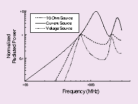 |
Figure 4. Impulse Response Between Two Non-Parallel Walls |
Figure 5. Radiated Power for a Dipole Antenna for Various Source Impedances |
Comparison testing, or comparing test A with test B (A-B tests), are frequently performed during EMC testing. These tests are of particular value when one part of a system is being changed. Rather than obtaining a full data set that identifies the entire system, an A-B test more clearly identifies the characteristics of the specific part that has been changed. Comparison tests also have the advantage of minimizing the effect of errors; most errors will be present in both the A and B tests, and will cancel in the final comparison.
Modeling can also take advantage of the improved accuracy like that available in comparison testing. In fact, comparative simulations are highly recommended for those just beginning to model EMI problems, and to help offset the difficulties associated with accurate source definition.
Today, relatively few detailed models are created with the intention of predicting regulatory style measurement results; rather, the focus is on understanding some specific portion of a product's behavior. Topics of study may include coupling between different parts of a system or leakage through apertures. To determine coupling based on size and separation of the component parts, a series of models can be constructed, each with slightly different dimensions. By examining the differences in coupling between such models, trends can be seen and suitable isolation maintained in the design. This can be done analytically for simple shapes but, for complex geometries, the only suitable tools available are the computational ones. The shielding provided by different size apertures can be estimated from the traditional shielding effectiveness equations but, when the source is closely coupled to the shield and/or when there are other conductors closely coupled, the results of these equations are meaningless. Here again a series of models can be created, the results compared, and used to determine the effects of changing aperture shape and size for the given geometry.
When measuring a device for emissions, the real source is part of the system, and does not need to be defined separately. It is not an uncommon practice to determine the shielding performance of a box by inserting a source into the empty box; however, it is understood that the real source might well behave very differently. To obtain valid results for the shielding, it is necessary to try and emulate the real source that will be in the system. The key attributes of the source are impedance and size. As shielding is the ratio of field strengths with and without the shield present, the amplitude of the source is not critical as long as it is known. The source impedance is very important in the determination of how much energy couples into the box, while the physical size determines how tightly the source and box are coupled.
There is a strong temptation to use ideal sources when modeling, but this can lead to some very large errors. For example, a dipole having a real resonant frequency of around 700 MHz is modeled using NEC. The goal of this model is to show how the total radiated power varies with three separate source impedances over a wide frequency range. The results of this model are shown in Figure 5.
The plots in Figure 5 are scaled so that they fit on the same graph. It can be seen that the ideal current source provides very different results from either the voltage source or the practical source impedance. The maximum for the current source occurs at the full-wave resonance where the antenna impedance is extremely high. In reality, it is extremely difficult to drive current into a full-wave dipole, and a minima would be expected rather than the peak. This minima can be clearly seen with both the voltage and practical source impedance.
For both measurements and modeling, an accurate representation of the noise source is critical if misleading results are to be avoided. One area of rapid growth for the use of EMI modeling is that of source modeling. The goal of these models is to provide accurate source information for system level computer models, and to support the need for building accurate physical models for experimental measurement work.
It is understood by all engineers that their measurements are not perfect. There are calibration uncertainties with every part of a measurement including the instrumentation, test environment, and variations in the individual units being measured. A realistic evaluation of these uncertainties is essential to the proper interpretation of the data obtained. Indeed, one of the skills in making accurate measurements is to correctly devise the test set-up in such a way that uncertainties are minimized.
In addition to the basic uncertainties that exist, there is a further complicating factor, namely repeatability. When measuring a voltage in a well-defined structure, it is expected that the same data will be obtained with very close correlation each time the measurement is made. When the electric field strength is measured at a distance of 10 m from a system that includes many devices and interconnecting cables, the same degree of correlation is not expected. While it is expected that the amplitude of the field strength would be close, it would not be expected that the field maximum would be measured with the antenna at exactly the same elevation, and with the system under test rotated to the same angle, especially at higher frequencies.
It is equally understood by engineers familiar with modeling that the results obtained from modeling will have some uncertainty associated with them. There is, however, a major difference in the source of these uncertainties. Unlike a complex physical measurement, repeating a complex computer model will always produce exactly the same answer; the real question with the modeling results is whether or not the actual model is correct.
There is a degree of uncertainty associated with the use of any modeling technique. This uncertainty results from the approximation of the model geometry into a digitized form, and a similar formulation of the appropriate equations into a form that can be solved computationally. If the inputs to a modeling technique are uncertain, or inaccurate, then the results will be inaccurate. When properly used, the accuracy of modern computational techniques is usually very high, and may even be used within a particular code to estimate the error. Simulation uncertainty can be most easily evaluated by using another solution code that utilizes a totally different formulation.
There are, however, other sources of uncertainty that are of greater importance, and are much harder to evaluate. While it is easy to create an accurate representation of the physical geometry of a device; it is not as simple to include its exact electrical properties. This is simply because the information is seldom known. In a physical system, real components provide the source of the RF energy; in a model, this source information has to be properly included. If the source of emissions is not fully represented in both amplitude and impedance, and, if necessary, in its physical dimensions, significant errors may result. Computer results usually reflect the model being solved very accurately; the uncertainty comes from the degree of correlation between the computer model and the practical implementation of the DUT.
The practical differences and similarities between EMI lab work and modeling have been discussed, bringing these two worlds a little closer together. While there are clearly some differences in the challenges faced by the engineer in the lab and the one working in front of the computer, both rely on understanding the physics of the problem, and having the experience to get the job done. The information given in this paper is intended to help provide confidence that what is being measured or modeled is really what is wanted, and not some other aspect of the problem.
Given the complexity of the EMC design and measurements, no one approach can be, or should be, relied upon exclusively to provide a full understanding. When supporting data is gathered from a variety of sources, an engineer can have greater confidence that it is both reliable and valid. Computer models and measurements can be used synergistically to provide insight to a particular issue, and they can be used in a complementary manner to ensure the validity and applicability.
Once the basic operation of an EMI modeling tool is understood, EMC engineers will find themselves in a very familiar world. This is a world where all experiments, both physical and simulated, must be carefully evaluated to ensure they are both valid and accurate; and where all results are treated only as a very good guide as to what is happening, rather than the final answer. Most importantly, it is a world that will continue to provide the EMC engineer with surprises and new challenges.
 |
Colin Brench has been working for Digital Equipment Corp., now Compaq Computer Corporation, for 15 years, where he is a Principal Member of the Technical Staff. He has responsibility for EMC product design, and the development of EMC modeling capabilities in the High Performance Server Division. Colin has been active in the area of antennas and EMC since the early 1970's. Colin is a co-author of the book, EMI/EMC Computational Modeling Handbook (Kluwer Academic, 1998), and has authored over 20 technical papers and articles. In addition, he holds eight patents for various methods of EMI control. He is a NARTE certified EMC Engineer, a member of the IEEE EMC Society, and is active in the TC-9 and ANSI ASC C63 SC-1 committees. In March of this year, Colin was appointed a Distinguished Lecturer for the IEEE EMC Society.
 |
Bronwyn Brench has run an EMC engineering consulting business since 1982. Her responsibilities include the management and operation of the business, and the reviewing and editing of technical papers, articles, and educational materials used for EMC training. Her latest project was technical reviewer and editor for the second edition of the book, EMI/EMC Computational Modeling Handbook (Kluwer Academic) due out in August 2001.
Bronwyn, in addition to being an at-home mother of two children, aged 14 and 16, with all that entails, has been working in the engineering field since 1976. She is a NARTE certified EMC Engineer, and is author of 13 technical papers and articles in the fields of EMC and photovoltaic systems. EMC
* All of the antenna models used to create Tables 1 and 2 were prepared using MiniNEC, the personal computer version of the well known Numerical Electromagnetics Code (NEC).