Henk A. Klok
Royal Netherlands Navy
Postbox 1260
2340 BG Oegstgeest
The Netherlands
phone: 00 31 71 305 2173
fax: 00 31 71 305 2606
e-mail: h.a.klok@hi.nl or adv@meobh.navy.dnet.mindef.nl
The use of Commercial off the Shelf equipment is widely accepted, even in a military electromagnetic environment. Since this equipment has to meet the European EMC-directive 89/336/EC, it is expected that in those cases where equipment needs to comply to the basic EMC-requirements a considerable amount of money will be saved.
In this paper, the differences between the military EMI-standard MIL-STD 461D/462D together with the civil EMI-requirements are compared with respect to measurement methods, frequency range and limits. Also the applicability of the test methods will be taken into account.
In the second place, the electromagnetic environment existing on board of Navy ships has been determined to evaluate the risk of using the COTS equipment in this environment. Within these established EM-environments the necessary EMC-requirements applied to the equipment are defined. A few of the assumptions made in the theoretical approach of the comparison are verified by using measurement data taken from commercial equipment.
It is noted that in case the necessary requirements could not be met with civil EMC standards, it is examined whether additional installation rules, or other additional constraints, would lead to the feasibility of using commercial equipment with a acceptable risk of EMI.
In the Royal Netherlands Navy a project is running to investigate and analyse the risk of installing commercial equipment in a military electromagnetic environment. Because of the fact that, in general, equipment fulfilling military EMC standards is expensive and that commercial equipment has to fulfil the EMC directive, it can be acceptable to install this equipment on board. However, it has to be taken into account that the environment of a naval ship is very different from an industrial and residential environment.
To investigate the difference and to prepare recommendations, the study will focus on a comparison of standards and environments.
The first step is to collect commercial standards, relating to electric and electronic equipment with respect to EMC requirements. Secondly, a comparison was made with the MIL-STD-461D/462D focusing on the frequency band of interest, the measurement methods, the limits, etc.
To analyse the risk by installing commercial equipment, the electromagnetic environment is determined and, with respect to this, conclusions can be made.
The main conclusion is that for operational and tactical equipment it is not allowed to
use commercial equipment. The frequency range of a ships EM-environment does not
correspond to the measuring frequency range for radiated emissions and immunity methods of
the civil standards. It can be recommended to civil organisations to at least extend the
frequency range. More investigations will perform to the installations rules on board if
stricter rules can partly solve this problem.
Another very important point will be to start discussions on the harmonisation of
measurement methods. When the methods are harmonised for the civil as well as the military
organisations, the limits can be different depending on the applicability, electromagnetic
environment, etc. of the equipment.
With respect to the commercial standards, several of them are included in the study:
The IEC 60533 is an interesting standard, applicable for electromagnetic compatibility of electrical and electronic installations in merchant ships. This makes a comparison with the military standards more in line of the naval ship's environment. The IEC 945 is a interference standard for navigation equipment installed in a ship's environment.
The other European EN standards are both generic standards for equipment not dealing with a product standard and installed in an industrial environment. EN 50081 is an emission standard, EN 80082 an immunity standard.
Comparing the commercial standards with the MIL-STD-461D/462D, it can easily be concluded that most of the tests are too different for a theoretically correct comparison. However since there is a need for a well founded stand regarding the application of commercial standards, one must make use of the experience, good practice and even experiments.
In general, the commercial standards differ from the military standards in two ways:
Below, the different methods and limits will be compared and discussed.
Focusing on the MIL-STD, it can be concluded that compared with the last versions (461C) of the MIL-STD, the D and E version use a Line Impedance Stabilisation Network (LISN) instead of a feedthrough capacitor.
This makes the comparison with the commercial standards more easy, because the civil standards also use a LISN. Before comparing the limit lines, some differences are to be noted:
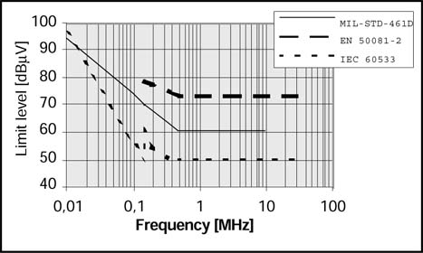
With these differences in mind, the limit lines over the common frequency range can be compared. This comparison shows that the IEC 60533 is more stringent than the other standards. See Graph 1 for the different limit lines. With respect to the IEC limit line it should be noted that this limit is for equipment installed in the bridge and deck zone. For equipment installed in the general power distribution zone the limit is about 20 dB less severe.
|
Graph 1: Comparison of conducted emission limits. |
In the harmonised commercial standards, only the electric field will be measured. There is a method under consideration for the magnetic field emission. The test method is very compatible with the MIL-STD-461/462.
In radiated emission tests for the electric field, the measuring distance and the environment are not similar.
The commercial standards require an open site environment, while the military standard requires a shielded room. The effect of the cage is responsible for a deviation to open site measurements results of maximum 6 dB.
However, the commercial standards are more open for the applicability for a screened room instead of the open area. Measurements in an open area are difficult to perform, due to the high ambient. To avoid reflections, a compact range (fully anechoic chamber) can be used.
This test environment makes a comparison easier, but special attention should be paid to performing radiated measurements in screened rooms. The results are very dependent on the amount of absorbing material in the room. Investigations and tests showed a difference of over 15 dB in different cages. When the cage is fully equipped with absorbing material with the proper specifications, the difference will increase to not more than 3 dB.
With respect to the measuring distance, in the commercial standards the distance in most cases is 30 metres, or sometimes, depending on the standard, 10 metres. In some cases a measuring distance of 3 metres is allowable.
In the IEC 60533 however, the measuring distance is 3 metres in all cases. Comparing with the MIL-STD measuring distance of 1 metres, the distance is a problem because of the fact that the antenna is placed in the near field.
In the commercial standards it should be noted that the limit can be corrected linearly as a function of the distance from 30 metres up to 3 metres (far field correction). For a measuring distance to 1 metre, the transfer function is frequency dependent due to near- and far-field corrections.
In the study this correction factor is calculated by assuming the fact that the field of the equipment under test is characterised as a field generated by a half wave dipole.
It is also important to note that the measured frequency range of most of the commercial standards is from 30 MHz to 1 GHz. Only in IEC 60533 is the starting frequency 150 kHz. This will be a very important change.
Comparing the different limits over the common frequency range, taking into account the differences in measuring distances, it is shown that the MIL-STD is more stringent than the commercial standards. For the comparison of the limits, see Graph 2.
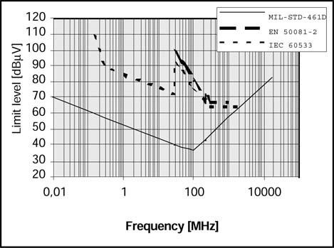 |
Graph 2: Comparison of radiated emission limits. |
It should also be noted that the frequency range of the MIL-STD is from 10 kHz up to 18 GHz.
Military and commercial standards are not really comparable because the injection methods are different.
An experiment could compare the injection methods by comparing the data resulting from a product investigation. A piece of equipment under test should be tested by both methods to determine if it conforms to the standards. During both tests the stress factor should be raised until the equipment under test fails. Comparing the stress factors should give information about the relation between the commercial and military standards.
The radiated susceptibility test with respect to the electric field, refers to a field measured at the location of the equipment under test. This causes no significant difference with the MIL-STD test.
An important difference will be the frequency range covered by both standards. In the MIL-STD the test has to be performed over a very wide frequency range from 10 kHz up to 40 GHz. In the commercial standards this will be from 30 MHz to 1 GHz (80 MHz to 2 GHz in the IEC 60533).
It can be concluded that the frequency range from 2 MHz to 30 MHz is not covered in the commercial standards.
Focusing on the limits of the different standards, it can be noted that equipment fulfilling the MIL-STD has to withstand 200 V/m over the complete frequency range for outerdeck purposes. For other purposes different values are applicable depending on the environment (below deck of a metal hull, non-metallic ship, etc.) and can be increased to 10 V/m. This is the same value as the commercial standard for industrial environment.
In the MIL-STD application, the test signal is unmodulated in the frequency range below 1 GHz.
Due to the modulation of 80 % with a 1 kHz signal the commercial test may be considered more severe than the MIL-STD for below deck equipment.
In this study special attention is paid to the frequency range below 30 MHz and above 1 GHz.
See Table 1 for an overview of the comparison.
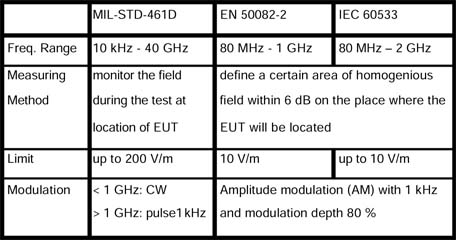 |
Table 1. Radiated Immunity comparison. |
The military environment differentiates itself from a commercial by radar transmissions, communications in a wide frequency range, electromagnetic pulse, and in inner deck situations by a high density of equipment.
In a commercial environment equipment is placed in an open field while the hull of a frigate provides a screening for the inner deck equipment against the outside world. This screening by the hull will create several areas with a different EM-environment, depending upon the quality of the screening.
The electromagnetic environment on board the Royal Netherlands Navy ships (due to the outside threat), is highly dependent upon the policy of the RNLN to build their own ships. The policy during the design of a ship is that the field strength inside the ship has to be as low as possible. To create an environment as �nice' as possible, installation rules are used. These rules are laid down in a Defence document KN 12330. This document is developed by the RNLN, based on theoretical measures and investigations to very practical guidelines.
Some of these are, for example:
These measures result in an EM-environment due to outside threats as radar, communications and EMP, which can be described as follows in Table 2.
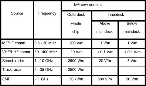 |
Table 2. Electromagnetic environment of a metal ship. |
A field strength below 1 V/m is considered as no threat. Regarding the above table, it seems that commercial equipment can be placed in below and inner deck areas, which have no direct link (by cable) to outer deck areas. However, in these situations the density of equipment in which the equipment has to work without EMI-problems should still be considered.
As already noted, the typical military EM-environment is caused by emissions from noisy inner deck equipment as static inverters at one hand and radar and communication transmitters outside at the other hand.
In most below deck areas the effect of the outside transmitters is negligible due to the installation rules. The concentration of equipment inside the ships hull is therefore considered a much greater danger.
Over the last five years commercial standards have been used incidentally on board RNLN ships. Up to now this has not resulted in a big problem, but it has to be taken into account that this was only valid for ships which are not acting as a real warship (frigate), such as an LPD or Oil Replenisher.
For frigates, the MIL-STD is the specification for all the equipment to be installed on board. In special cases, on request of the manufacturer, it is allowed to deliver equipment which fulfils the commercial standard, but some additional tests have to be performed to make sure that no problems will arise when installing these.
During a part of the study, manufacturers were invited to have a CE-marked product tested to conform to the commercial standard tested to conform to the military standard as well. About one hundred manufacturers were invited of which twenty five responded. Most of them are active in the control, monitoring and in the static inverter industry. All manufacturers have contacts with the RNLN and should have been aware of EMC-requirements.
As a result it can be noted that in some cases, in the frequency range below 30 MHz radiated problems (due to both emission and immunity) were found.
This underlined the importance of having radiated limits for emissions as well as susceptibility tests in the HF-range from 1 MHz to 30 MHz.
So, the product investigations showed that most of the emitted energy is below 30 MHz and this is not covered in the commercial standards except the IEC 60533.
That is one part of the hardening, the other part is of course the susceptibility to electric fields, which is not implemented in the commercial standards.
A risk is taken when relying fully on the CE-marking of a product. The product investigation showed that not all equipment complies to the required standards. This is assumed to be a short term effect. To minimise the risk it is advisable to add EMC-tests to the factory acceptance tests.
From a technical point of view, it can be concluded that the commercial standards do not cover the military environment as the MIL-STD does. The IEC-60533 is the most comparable standard which can be used, but with respect to the radiated immunity, also the IEC does not cover the military environment over the whole frequency range, so still problems can be expected.
As a commercial conclusion, it can be noted that the use of commercial EMC-standards as a way to save money, influences the safety margin by an unknown factor. This causes an undefined environment and just saves a considerable amount of money for large quantity of goods, bought off the shelf. Unfortunately there is no way to know if these savings are in balance with possible costs to solve EMI-incidents for ships beyond the period of guarantee.
Saving costs and having a defined environment can be established by specifying engineering requirements and having the tests done by the Navy itself.
Regarding the applicability of commercial standards the following can be stated at this moment:
For current projects as well as for future projects it is very important to specify the EMI/EMC-requirements in an early phase. It is recommended to specify only the MIL-STD-461D/462D or MIL-STD 461E.
When a manufacturer offers commercial equipment, additional tests have to be performed to check if the desired standards are sufficient, taking into account the place of installation and the electromagnetic environment there.
Very important for this additional test is the frequency range of interest. Special care should be taken of the frequency range of 1 MHz to 30 MHz.
To minimise the risk it is therefore advisable to add these EMC-tests to the factory acceptance tests.
A last point, and in the opinion of the defence organisation a very important point, is the discussion on the harmonisation of, at least, measuring methods.
The study has shown that the differences in test methods for commercial and military standards are that big, that comparison is rather impossible. It will be a big step in a good direction if at least the measuring methods of the military and the commercial standards are the same. It is well known that some defence organisations started a discussion on this item, but it appears that it will be a very long way to go.
The methods can be the same over the total frequency range of threat for the commercial world as well as the military world.
With respect to the limitation, different limits can be proposed for the different environments.
It is expected that equipment installed in an industrial environment in a ground facility without transmitters in the neighbourhood, has to fulfil other limits and to meet other EM-requirements, than equipment installed in a navy environment with a lot of radar- and communication transmitters on board the same platform.
As a starting point for further discussion, find below a proposal for the measurement methods to be performed as a minimum. The methods cover the whole frequency range of the total EM-environment for all applications.
Further discussions can be focused on the method itself, for example what LISN shall be used, measuring voltage or current, magnetic field and electric field, frequency range, measuring distances, etc.
Before starting discussions on the limits, the methods have to be agreed upon by all bodies, civil as well as military.
 |
Henk A. Klok has worked in the electromagnetic area since 1980. He graduated in Electrical Engineering at the Institute of Technology of The Hague in the Netherlands. He is now working as a senior adviser in the Electromagnetic Environment Effects (E3) area in the Royal Netherlands Navy. He specialises in Naval EM-engineering, EMC/EMI control, topside design of maritime platforms and radiation hazards. He is a member of different NATO-groups working in that special EM-area. He also recently became a member of the national EMC institute in the Netherlands. |