Welcome to Design Tips! It is well known that high speed signal traces should not cross a split in the nearest ground-reference plane. However, due to PCB cost/space constraints, we are often forced to route such traces adjacent to power layers, where various power islands exist. If a high speed trace travels from the region of one power island to another, it effectively crosses a split in the nearest reference plane. In the last Design Tips article (published in the Spring 2011 issue of the EMC Newsletter), Professor Jun Fan from the Missouri University of Science & Technology discussed Near End Cross Talk (NEXT) due to the effect
|
of traces crossing splits in the reference plane. In this Design Tip, Professor Fan discusses how to estimate the impact on the Far End Cross Talk (FEXT) crossing between two traces.
Please send me your most useful design tip for consideration in this section. Ideas should not be limited by anything other than your imagination! Please send these submissions to bruce.arch@ieee.org. I’ll look forward to receiving many “Design Tips!” Please also let me know if you have any comments or suggestions for this section, or comments on the Design Tips articles. |
Far-End Crosstalk
By Jun Fan, Missouri University of Science and Technology, jfan@mst.edu
In the last issue of Design Tips, I discussed how to estimate the crosstalk between two stripline traces crossing a split in one of the reference planes [1]. The near-end crosstalk was studied using a decomposition approach, and thus the direct trace-to-trace coupling and the split-related coupling could be investigated separately. In this issue, I would like to continue with the far-end crosstalk (FEXT).
 |
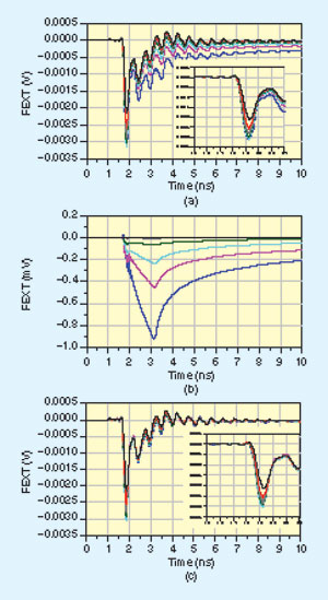 |
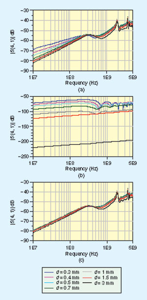
Fig. 1. |S41| as a function of trace-to-trace separation.
(a) |S41|Overall (b) |S41| Due to direct trace-to-trace coupling
(c) |S41|Due to split-related coupling. |
Fig. 2. FEXT as a function of trace-to-trace separation.
(a) Overall FEXT (b) FEXT due to direct trace-to-trace coupling (c) FEXT due to split-related coupling. |
The test structure is exactly the same as that shown in [1], [2]. The overall magnitudes of the frequency-domain FEXT (|S41|) with various trace-to-trace separations (d) are shown in Fig. 1 (a). Using the same decomposition approach, the FEXT components due to the direct trace-to-trace coupling and the split-related coupling are shown in Fig. 1 (b) and (c), respectively. It can be seen that, when d is smaller than 0.7 mm, the overall crosstalk magnitude is dominated by the trace-to-trace coupling, but only at the frequencies lower than 200 MHz. Beyond this frequency, the overall crosstalk is dominated by the split-related coupling. This is because, in a homogeneous medium, the FEXT due to the direct trace-to-trace coupling is very small in magnitude because of the cancellation of the inductive and capacitive coupling. When the distance between the two traces is greater than 0.7 mm, the FEXT magnitude is dominated by the split-related coupling in the entire frequency range of interest.
Based on the same decomposition procedure, the corresponding FEXT waveforms in the time domain are shown in Fig. 2, where the rise time of the aggressor voltage is 200 ps and both traces are matched at the ends. Unlike the NEXT, the magnitudes of the FEXT waveforms due to the direct trace-to-trace coupling are smaller than those due to the split-related coupling. This is because of the cancellation of the inductive and capacitive coupling as mentioned earlier. As shown in Fig. 2 (c), the split–related FEXT waveforms for different d values have a similar shape, while the peak values are slightly different.
From both the frequency- and time-domain discussions, we can see that the FEXT between the two traces is mostly dominated by the split-related coupling, which is not a strong function of the trace-to-trace separation. Similarly, as in the NEXT case, the dimensions of the split contribute to the resonances in the frequency domain and oscillations in the time domain, which could become a trouble maker for sensitive signals when the aggressor signal has large spectral components at these resonant frequencies.
Some signal integrity engineers believe that the FEXT due to the direct trace-to-trace coupling is always cancelled, as demonstrated in this example. Is this correct? By playing with the multi-conductor transmission-line theory [3], it can be shown that, for homogeneous, lossless (low-loss), weakly-coupled, and matched transmission lines, the FEXT among them can be approximately cancelled. Typical stripline traces in multilayer printed circuit boards satisfy these conditions; thus cancellation of FEXT can be often observed by PCB designers.
But if one or more of these conditions are not met, can FEXT still be cancelled? It can be further shown that there exists a more general condition for the exact cancellation of the FEXT between two homogeneous and lossless (low-loss) transmission lines as
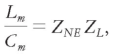
where Lm and Cm are the per-unit-length mutual inductance and mutual capacitance between the aggressor and the victim lines; ZNE is the termination of the victim line at the near end close to the aggressor excitation; and, ZL is the termination of the aggressor line at the far end. It is interesting to see that this general condition has nothing to do with the characteristic impedances of the aggressor and the victim lines, and is not affected by the other terminations either.
As long as the general condition is satisfied, the FEXT between two homogeneous and lossless transmission lines can be exactly cancelled. Readers may come up with some creative designs to meet this cancellation condition, if minimizing far-end crosstalk is desirable.
References
[1] J. Fan, “Crosstalk estimation for stripline traces crossing a split,” IEEE EMC Society Newsletter, Issue No. 229, Spring 2011, pp. 69–71.
[2] S. Wu, M. Herndon, H. Shi, B. Cornelius, and J. Fan, “Crosstalk among multiple stripline traces crossing a split,” DesignCon 2011, Santa Clara, CA,
January 31–February 3, 2011.
[3] C. Paul, Introduction to Electromagnetic Compatibility, John Wiley and Sons, 2006.
Biography
 Jun Fan (S’97-M’00-SM’06) received his B.S. and M.S. degrees in Electrical Engineering from Tsinghua University, Beijing, China, in 1994 and 1997, respectively. He received his Ph.D. degree in Electrical Engineering from the University of Missouri-Rolla in 2000. From 2000 to 2007, he worked for NCR Corporation, San Diego, CA, as a Consultant Engineer. In July 2007, he joined the Missouri University of Science and Technology (formerly University of Missouri-Rolla), and is currently an Assistant Professor with the Missouri S&T EMC Laboratory. His research interests include signal integrity and EMI designs in high-speed digital systems, dc power-bus modeling, intra-system EMI and RF interference, PCB noise reduction, differential signaling, and cable/connector designs. Dr. Fan served as the Chair of the IEEE EMC Society TC-9 Computational Electromagnetics Committee from 2006 to 2008, and was a Distinguished Lecturer of the IEEE EMC Society in 2007 and 2008. He currently serves as the Vice Chair of the Technical Advisory Committee of the IEEE EMC Society. Dr. Fan received an IEEE EMC Society Technical Achievement Award in August 2009. EMC Jun Fan (S’97-M’00-SM’06) received his B.S. and M.S. degrees in Electrical Engineering from Tsinghua University, Beijing, China, in 1994 and 1997, respectively. He received his Ph.D. degree in Electrical Engineering from the University of Missouri-Rolla in 2000. From 2000 to 2007, he worked for NCR Corporation, San Diego, CA, as a Consultant Engineer. In July 2007, he joined the Missouri University of Science and Technology (formerly University of Missouri-Rolla), and is currently an Assistant Professor with the Missouri S&T EMC Laboratory. His research interests include signal integrity and EMI designs in high-speed digital systems, dc power-bus modeling, intra-system EMI and RF interference, PCB noise reduction, differential signaling, and cable/connector designs. Dr. Fan served as the Chair of the IEEE EMC Society TC-9 Computational Electromagnetics Committee from 2006 to 2008, and was a Distinguished Lecturer of the IEEE EMC Society in 2007 and 2008. He currently serves as the Vice Chair of the Technical Advisory Committee of the IEEE EMC Society. Dr. Fan received an IEEE EMC Society Technical Achievement Award in August 2009. EMC
|
 Design Tips