Bob Rothenberg,
Associate Editor
| Two interesting papers are presented in this issue. The first, by Jim Muccioli of Jastech EMC Consulting, describes EMC measurements on dual line filters using a simple current injection test method. The second, by Scott Bennett, an EMC Consultant in Carr, Colorado, describes a useful and basic approach for minimizing fields from electrical circuits. The Bennett paper is an outgrowth of presentations he has given recently at EMC Society chapter meetings in Oregon/SW Washington and Seattle. Practicing members of the EMC community are encouraged to share their experience-based knowledge by submitting articles or application notes for publication in this section of the Newsletter. Unlike Transactions papers, these works need not be theoretical, mathematical or archival. Test methods, measurement results and design approaches are particularly suitable. Maximum length is approximately 2000 words, plus up to 6-8 figures (depending on word count). Submit articles for consideration to this Associate Editor via e-mail, fax or airmail. |
by James P. Muccioli
The purpose of this article is to present a test method for dual line filter measurements of common and differential mode noise using a small current probe. This test method is similar to the MIL-STD-461 “Current Injection Insertion Loss Measurement Method,” however two lines are tested simultaneously and modifications are made to the probe and cable lengths for measurements up to 1000 MHz. Data is developed with several different types of filter configurations to characterize the test method.
In today’s EMC environment, where both common and differential mode noise need to be reduced, there are very few test procedures that measure the results of a dual line filter in its dynamic state. Typically, a dual line filter is tested in a static state, where one side is tested and then the other side, showing the insertion loss of each line but not both simultaneously. The author will describe a simple test methodology in which a spectrum analyzer with a tracking generator and a current probe is used for dynamic testing of the dual line filter.
 |
Figure 1. Measurement test setup. |
 |
Figure 2. Three different dual line filter configurations. |
The test setup is shown in Figure 1. Three different dual line filter configurations are used for the device under test (DUT), as shown in Figure 2. The DUT is characterized using the tracking generator from the spectrum analyzer as the noise source for the before and after measurements. The tracking generator is connected to a power divider so both sides will receive equal amounts of noise. The actual test is conducted using a quart paint can to isolate the fields before and after the filter, as shown in Figure 3. The different filter configurations are attached to the top of the paint can and the wires protrude through the top of the paint can and terminate to a 50-W load. The small current probe is used to measure line A, line B, and then both lines A+B before the filter. Then the top is placed on the paint can and line A’, line B’, and lines A’+B’ are measured.
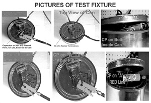
Figure 3. Pictures of test fixture.
Figure 4. Current probe transfer impedance factor.
The purpose for using a miniature current probe (Fischer Custom Communications F-36-4) is to make quantitative measurements of the currents (magnetic fields) generated by the electrical noise from the tracking generator on the transmission lines. The current probe can be used in a non-shielded room because only the magnetic fields related to the electromagnetic radiation potential of the tracking generator affect the probe and it is relatively insensitive to stray electric fields. The windings of the probe are in a shield that reduces E-field pickup. Typical values of shielding from external E-fields vary from 60 dB below 100 MHz to greater than 30 dB at 450 MHz.
The current probe has transfer impedance from 100 kHz to 1000 MHz, as shown in Figure 4. The transfer impedance Zt is defined as the ratio of voltage developed across the output of the probe to the conductor under test. The current IP in the conductor is calculated from the current probe output ES in volts divided by the probe transfer impedance Zt:
IP = ES/Zt (Equation 1)
The spectrum analyzer used in this test is an IFR AN920 (9kHz - 2.9 GHz) and the frequency range is set from 100 kHz to 1000 MHz. The resolution is set to 120 kHz and the video bandwidth is turned off so that the spectrum analyzer does not filter the signals being analyzed.
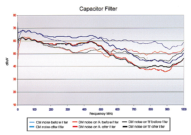
Figure 5. Capacitor filter.
In Figures 5 through 10, the thin lines are the baseline references before the filter is introduced and the heavy lines are the measurements taken after the filter is in place. The delta between the baseline (before) and after filter measurements in these figures is the insertion loss in dBuV.
Figure 5 shows that a normal capacitor placed across lines A & B produces very little insertion loss over the frequency range. Below 150 MHz there is no insertion loss due to the filter. Between 150 MHz and about 500 MHz, there is a negative insertion loss (amplification of the noise). Finally, above 550 MHz, the data shows 2 to 15 dBuV of insertion loss.

Figure 6. 3-pole capacitor filter.
Figure 6 shows the test results using a 3-pole capacitor filter. There is 10 to 40 dBuV of common and differential mode noise insertion loss, depending on frequency. A dip in the baseline values above 800 MHz is due to the wire length of 4.25 inches and movement of the wire to the side of the paint can, which causes resonance.
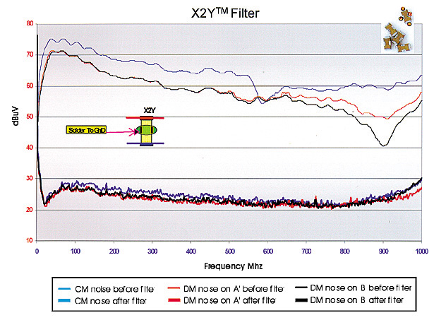
Figure 7. X2Y filter.
Figure 7 shows that the X2Y filter provides between 20 and 54 dBuV of insertion loss over the frequency range tested for both common mode and differential mode.
In Figures 8, 9, and 10, the baseline data for both the 3-pole capacitor filter and the X2Y filter are very similar. The X2Y filter provides better common and differential mode insertion loss over the frequency range tested.
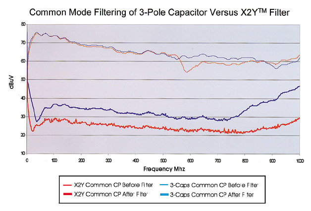
Figure 8. Common mode noise filtering of 3-pole capacitor filter compared to a X2Y filter
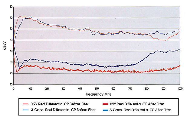
Figure 9. Differential mode noise filtering of line "A" with a 3-pole capacitor filter compared to an X2Y filter.
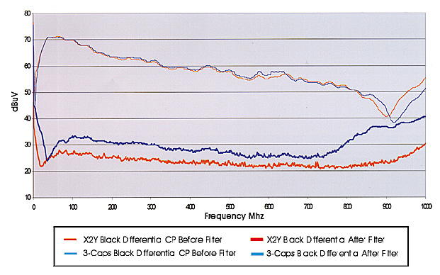
Figure 10. Differential mode noise filtering of line "B" with a 3-pole capacitor filter compared to an X2Y filter.
The test methodology used to measure the dual line filters is repeatable and easy to run. The current probe used in this test procedure was very effective in measuring both common mode and differential mode noise. However, the wire length of 4.25 inches needs to be reduced to eliminate high frequency resonance effects.
In summary, both the 3-pole filter and the X2Y device proved very effective in reducing common and differential mode noise. When EMC requirements are too stringent for normal capacitors, the X2Y device can provide added insertion loss.
This study was conducted with the filter values mentioned. The filtering can be improved by optimizing the filter value for any particular application. The load network in this test was built to 50-W impedance, but can be changed to meet any specific load requirements.
I would like to thank Joe Fischer from Fischer Custom Communications, Inc. (https://www.fischercc.com/) for supplying the calibrated current probe used in the test setup. I would also like to thank Tony Anthony from X2Y Attenuators, LLC (https://www.x2y.com/) for supplying samples of the X2Y device manufactured by Syfer Technology Limited (https://www.syfer.com/).
 James Muccioli is associated with Jastech EMC Consulting, LLC and X2Y
Attenuators, LLC. He has extensive experience in EMC design, analysis, and testing. He is
a NARTE certified EMC and ESD engineer, an active member of SAE J-1113 and J-551 EMC
committees, and chairman of the SAE Integrated Circuit EMC Task Force. He was selected as
an IEEE Fellow in 1998 for contributions to integrated circuit design practices to
minimize electromagnetic interference. Mr. Muccioli teaches seminars on EMC through his
consulting firm, Jastech EMC Consulting, LLC (www.Jastech-emc.com)
and an undergraduate course on EMC at the University of Michigan-Dearborn. He can be
reached by e-mail at: jastech@ameritech.net.
James Muccioli is associated with Jastech EMC Consulting, LLC and X2Y
Attenuators, LLC. He has extensive experience in EMC design, analysis, and testing. He is
a NARTE certified EMC and ESD engineer, an active member of SAE J-1113 and J-551 EMC
committees, and chairman of the SAE Integrated Circuit EMC Task Force. He was selected as
an IEEE Fellow in 1998 for contributions to integrated circuit design practices to
minimize electromagnetic interference. Mr. Muccioli teaches seminars on EMC through his
consulting firm, Jastech EMC Consulting, LLC (www.Jastech-emc.com)
and an undergraduate course on EMC at the University of Michigan-Dearborn. He can be
reached by e-mail at: jastech@ameritech.net.