Page 5 - SE_Approach_for MSEE_MSCE_Capstone_15_Page_review2
P. 5
2016 ASEE Rocky Mountain Section Conference
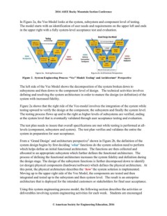
In Figure 2a, the Vee-Model looks at the system, subsystem and component level of testing.
The model starts with an identification of user needs and requirements on the upper left and ends
in the upper right with a fully system-level acceptance test and evaluation.
The left side of the Vee Model shows the decomposition of the system broken down to
subsystems and then down to the component level of design. The technical activities involves
defining and resolving the system architecture in order to mature the design (or definition) of the
system with increased fidelity.
Figure 2a shows that the right ride of the Vee-model involves the integration of the system while
testing upward to verify the design at the component, the subsystem and finally the system level.
The testing process flows up and to the right as higher levels of subsystems are verified, ending
at the system level that is eventually validated through user acceptance testing and evaluation.
The test plan needs to insure that overall specifications are met while testing is performed at all-
levels (component, subsystem and system). The test plan verifies and validates the entire the
system in preparation for user acceptance.
From a ‘Grand Design’ and architecture perspective2 shown in Figure 2b, the definition of the
system design begins by first deciding ‘what’ functions do the system solution need to perform
which helps define an initial functional architecture. The functions are then collected and
allocated to an appropriate subsystem which further defines the functional architecture. The
process of defining the functional architecture increases the system fidelity and definition during
the design stage. The design of the subsystem functions is further decomposed down to identify
(or design) physical components (hardware/software) which defines the physical architecture. At
this point, the physical architecture describes the ‘how’ the system solution is implemented.
Moving up to the upper right side of the Vee Model, the components are tested and then
integrated and tested up to the subsystem and then system level. The result is an enterprise
architecture that is deployed for the intended customers or stakeholders for final user acceptance.
Using this system engineering process model, the following section describes the activities or
deliverables involving system engineering activities for each week. Students are encouraged
© American Society for Engineering Education, 2016